Open post

genie 2028 manual

Genie 2028⁚ A Comprehensive Guide

This guide provides a complete overview of the Genie 2028 garage door opener. It covers installation, operation, maintenance, programming, troubleshooting, safety, and compatibility with smart home systems. Find answers to your questions and access downloadable manuals here.

Introduction to the Genie 2028 Model

The Genie 2028, part of the ReliaG Pro Series, is a reliable and powerful garage door opener valued for its performance and features. This model incorporates a DC motor with a smooth soft start and stop function, ensuring quiet and efficient operation. The opener’s speed is impressive, reaching up to 7 openings per second, making it a convenient choice for busy households. The Genie 2028 boasts HomeLink and Car2U compatibility, allowing for seamless integration with your vehicle’s remote system. Safety is a priority, incorporating safety beams to prevent accidents. Comprehensive manuals are available for both installation and operation, guiding users through setup and maintenance procedures. Users can find these resources online or through Genie customer support. The model’s design balances power, value, and dependability, making it a popular choice among homeowners. This model also offers several convenience options, enhancing the user experience and providing a superior level of functionality.

Key Features and Benefits of the Genie 2028

The Genie 2028 garage door opener stands out due to its powerful DC motor, providing a smooth, quiet, and efficient operation. The soft start and stop features minimize noise and prevent jarring movements, extending the lifespan of both the opener and the garage door. Its speed is a significant advantage, with the capability to open and close the door up to seven times per second, significantly reducing waiting time. The Genie 2028 also incorporates safety features like the essential Safe-T-Beam system, ensuring protection for people and property. HomeLink and Car2U compatibility allow effortless integration with your vehicle’s remote, providing added convenience. The Intellicode remote control system enhances security and prevents unauthorized access. Moreover, the Genie 2028 is designed for residential use with sectional overhead garage doors, making it suitable for most homes. Its user-friendly design and comprehensive manual ensure ease of installation and operation. The combination of power, reliability, safety, and convenience makes the Genie 2028 a top choice among homeowners.

Installation Guide and Setup Procedures

Before beginning the Genie 2028 installation, ensure you have all necessary tools and components. Carefully read the entire manual to understand the process. Begin by securely mounting the motor unit to the ceiling or wall, following the provided guidelines for proper alignment and stability. Connect the power supply and ensure a firm electrical connection. Attach the chain or belt drive system to the motor and the garage door, maintaining correct tension. Next, install the safety sensors (Safe-T-Beam) on both sides of the garage door opening, ensuring proper alignment and functionality. Program the remote control transmitters according to the manual’s instructions. Test the opener’s operation, verifying that the door opens and closes smoothly and stops immediately upon encountering an obstruction. Consult the manual for troubleshooting any issues during installation. Following these steps carefully will ensure a safe and functional installation of your Genie 2028 garage door opener. Remember to always prioritize safety throughout the installation process.

Operation and Maintenance Manual⁚ Essential Information

Regular maintenance is crucial for optimal performance and longevity of your Genie 2028 garage door opener. This section details essential operational procedures and maintenance tasks. Familiarize yourself with the opener’s control panel and its various functions, including opening, closing, and lighting. Learn how to utilize the different operational modes, such as the soft start/stop feature, if equipped. Regularly inspect the tracks, rollers, and springs for any signs of wear and tear or damage. Lubricate moving parts as recommended in the manual using appropriate lubricants. Check the safety sensors (Safe-T-Beam) to ensure they are clean and aligned correctly. Periodically inspect the chain or belt drive system for proper tension and replace if necessary. Clean the motor unit housing and surrounding area to remove dust and debris. Address any operational issues promptly by referring to the troubleshooting section of the manual. Preventative maintenance, such as regular lubrication and inspection, will significantly extend the life of your Genie 2028 and ensure its safe and reliable operation. Remember to consult the full manual for detailed instructions and safety precautions.

Programming Your Genie 2028 Opener

Programming your Genie 2028 garage door opener involves adding new remotes, keypads, or HomeLink systems. The process typically involves locating the “learn” button on the opener’s motor unit. This button initiates the programming mode. Next, you’ll need to press and hold a button on the new remote or keypad while simultaneously activating the learn button on the motor unit. The opener’s indicator light will usually flash to confirm successful programming. Consult the manual for specific instructions on programming different types of devices. The manual will detail the exact steps for programming Genie Intellicode remotes, keypads, and other accessories. It might also include instructions for programming HomeLink compatible vehicles. If you encounter issues during programming, double-check the manual for troubleshooting steps or contact Genie customer support for assistance. Remember that successful programming requires precise timing and adherence to the steps outlined in the manual. The manual provides detailed illustrations and clear instructions to guide you through the process. Properly programming your Genie 2028 ensures secure and convenient operation.

Troubleshooting Common Issues with the Genie 2028

If your Genie 2028 garage door opener malfunctions, the first step is to consult the troubleshooting section of the owner’s manual. Common problems include the door not opening or closing, intermittent operation, or the opener making unusual noises. The manual will guide you through checking power supply, ensuring proper door alignment, and inspecting the safety sensors. Issues with the safety sensors are a frequent cause of malfunction. The manual usually includes detailed instructions on how to test and clean these sensors. If the door is not closing properly, obstructions in the door’s path should be removed. A malfunctioning remote control may also be a cause. The manual provides instructions on how to reprogram or replace the remote. If the opener is making unusual noises, such as grinding or clicking, this may indicate a mechanical issue. Inspect the chain or belt drive for any signs of damage or wear. For persistent problems that you cannot solve using the manual, contact Genie customer support for professional assistance. They can provide expert guidance and potentially schedule a service call if necessary. Remember to always prioritize safety and disconnect the power before performing any physical checks or repairs.

Safety Features and Precautions

The Genie 2028 incorporates several safety features designed to protect users and their property. The most crucial is the automatic reverse system, which stops the door’s movement if it encounters an obstruction during closing. This is essential for preventing injuries to people or pets. Regular testing of the safety sensors is vital to ensure this system functions correctly. The sensors should be cleaned regularly to maintain optimal performance. Never operate the opener if the sensors are malfunctioning or damaged. The manual provides detailed instructions on how to test and align the sensors. Another important feature is the rolling code technology which enhances security by constantly changing the code used to operate the opener, making it more difficult for unauthorized individuals to access your garage. Always keep the remote controls out of reach of children. Never allow children to play near the garage door while it is operating. Ensure that the garage door is properly balanced and lubricated to prevent strain on the opener motor and reduce the risk of accidents. Regular maintenance, as detailed in the manual, is vital for maintaining the safety features. If you notice any unusual behavior or noises from the opener, discontinue use and contact Genie customer support for assistance. Prioritizing safety ensures the long-term operation of your Genie 2028 and avoids potential risks.

HomeLink and Car2U Compatibility

The Genie 2028 is designed for seamless integration with popular vehicle systems, offering convenient garage door control directly from your car. HomeLink, a built-in system in many vehicles, allows you to program your Genie 2028 opener to a button on your car’s visor. This eliminates the need to use a separate remote control, providing a streamlined and user-friendly experience. The programming process is typically straightforward, and detailed instructions are available in your vehicle’s manual and on the Genie website. Car2U is another compatible system, offering similar functionality. Consult your car’s manual to determine if it supports HomeLink or Car2U and follow the specific instructions for programming your Genie 2028 opener. Successful integration will allow you to open and close your garage door with a simple press of a button on your car’s dashboard. Remember to consult the Genie 2028 manual for troubleshooting if you encounter difficulties during the programming process. Proper programming ensures that the system functions reliably and provides the convenience intended. This feature significantly enhances the overall user experience, adding a layer of ease and efficiency to daily garage access.

Smart Home Integration with Genie 2028

Enhance your home automation setup by integrating your Genie 2028 garage door opener into your smart home ecosystem. This allows for convenient control and monitoring through various smart home platforms and applications. Many users find this feature particularly beneficial for remote access and scheduling. Check the Genie website for compatible platforms such as Google Home, Amazon Alexa, and Apple HomeKit. Once you have confirmed compatibility, follow the instructions provided by Genie and your chosen smart home platform for seamless integration. Through this integration, you can control your garage door using voice commands, schedule automatic opening and closing times, and receive notifications about the garage door’s status. This integration can also be useful for security purposes. For example, you can receive alerts if the garage door is left open unexpectedly. The Genie 2028’s smart home capabilities elevate its functionality, contributing to a more convenient and secure home environment. Remember to consult the Genie 2028 manual and the documentation for your specific smart home platform for detailed instructions and any troubleshooting steps you might require.

Accessing and Downloading Manuals

Accessing comprehensive documentation for your Genie 2028 garage door opener is straightforward. The manufacturer’s website, GenieCompany.com, serves as the primary resource for all manuals and support documents. Navigate to their product support section, typically found under a “Support” or “Downloads” tab. You’ll need to specify your model number, 2028, to filter the results and locate the relevant documents. The website offers various manuals in PDF format, ensuring easy download and offline access. These manuals cover a wide range of topics, including installation, operation, maintenance, programming, and troubleshooting. Always ensure you download the latest version of each manual to benefit from the most up-to-date information and safety guidelines. In addition to the official website, you may find copies of the Genie 2028 manual on third-party websites offering user manuals and technical documentation, but always verify the authenticity and version to avoid outdated or incorrect information. Should you encounter any issues accessing or downloading the manuals, contacting Genie’s customer support directly is recommended for prompt assistance.

Genie 2028 Replacement Parts

Maintaining your Genie 2028 garage door opener’s optimal performance often requires replacing worn or damaged components. Fortunately, sourcing replacement parts is relatively easy. The Genie Company’s website is a great starting point. Their online store typically lists available parts for the 2028 model, allowing you to browse and order directly. You’ll find parts categorized by function, making it simple to identify what you need. When ordering, always double-check the part number to ensure compatibility with your specific opener. Alternatively, authorized Genie dealers and retailers often stock common replacement parts. Checking with local hardware stores or home improvement centers that carry Genie products could save you shipping time and costs. Before purchasing any part, it’s advisable to consult your Genie 2028 manual for diagrams and part numbers to accurately identify the needed component. If you’re uncertain about the part you need or its installation, contacting Genie customer support for guidance is always a good idea. They can offer expert advice, ensuring you get the correct part and install it correctly to avoid further damage or safety hazards. Remember to always prioritize using genuine Genie replacement parts to maintain the warranty and ensure proper functionality.

Contacting Genie Customer Support

Should you encounter any difficulties with your Genie 2028 garage door opener, accessing reliable customer support is crucial. The Genie Company offers multiple avenues for assistance. Their website, www.GenieCompany.com, provides a comprehensive FAQ section addressing common issues. You’ll find troubleshooting guides, installation instructions, and answers to frequently asked questions. If your problem isn’t addressed in the FAQ, the website also typically features contact information for customer support representatives. This might include a phone number, email address, or an online contact form. A phone call often provides the quickest resolution, especially for urgent problems. The provided number, often 1-800-35-GENIE (1-800-354-3643), connects you directly to trained technicians who can guide you through troubleshooting steps or schedule a service appointment if necessary. Remember to have your model number (2028) readily available when contacting support to streamline the process. For less urgent inquiries, using the email or online contact form allows for a detailed description of the issue and provides a record of the communication. Whether you choose phone, email, or online contact, be prepared to provide relevant information, such as the model number, date of purchase, and a clear description of the problem. Genie’s customer support aims to provide prompt and effective solutions to ensure your garage door opener functions safely and reliably.

Open post

manual coats tire changer

Manual Tire Changer⁚ A Comprehensive Guide

This guide provides a comprehensive overview of manual tire changers, covering their advantages, types, selection, components, safety, operation, maintenance, troubleshooting, and purchasing resources․ It aims to equip users with the knowledge for safe and efficient tire changes․

The versatility of manual tire changers extends to their suitability for various tire sizes, from small motorcycle tires to larger car and light truck tires․ Many models boast adjustable components to accommodate different rim diameters and tire widths․ This adaptability is a key advantage for users dealing with a range of vehicles or applications․ Furthermore, the hands-on nature of using a manual tire changer can provide a deeper understanding of the tire-to-wheel interface and the mechanics involved in tire mounting and dismounting, which can be valuable knowledge for anyone working with tires․ However, it’s crucial to understand and adhere to safety precautions to avoid injuries or damage to the equipment․

Advantages of Manual Tire Changers over Automatic Models

Manual tire changers offer several key advantages over their automatic counterparts, primarily revolving around cost and portability․ The initial purchase price of a manual model is significantly lower, making them an attractive option for individuals or small businesses with limited budgets․ Their compact size and relatively light weight (around 32 lbs for some models) allow for easy transport and storage, unlike larger, heavier automatic machines․ This portability is especially beneficial for mobile tire repair services or for use in locations with limited space․ Furthermore, manual changers often require less maintenance and have fewer parts that can malfunction compared to more complex automatic systems, leading to reduced downtime and repair costs․ The simplicity of their design also makes them easier to understand and use, reducing the learning curve and the need for specialized training․

While automatic tire changers offer speed and ease of use for high-volume applications, manual models provide a degree of control and precision that some users prefer․ The user has direct control over the process, which allows for more careful handling of delicate rims and tires․ This is particularly important when working with high-performance or specialty tires․ In addition, the lack of reliance on electricity or compressed air means that manual tire changers can be used virtually anywhere, regardless of power availability or air compressor access․ This independence is a significant advantage in remote locations or during power outages․ These factors make manual tire changers a robust and practical choice for many individuals and businesses․

Types and Sizes of Manual Tire Changers

Manual tire changers come in a variety of types and sizes, catering to different needs and applications․ The most common distinction is between those designed for smaller tires, such as those used on motorcycles, ATVs, and bicycles, and those capable of handling larger car and light truck tires․ Motorcycle tire changers are typically more compact and lightweight, often featuring a simpler design․ Car and light truck tire changers are usually larger and more robust, with more substantial components to handle the greater forces involved in changing larger, heavier tires; Some models are specifically designed for run-flat tires, which require specialized tools and techniques for mounting and dismounting․

The size of a manual tire changer is primarily determined by the maximum rim diameter it can accommodate․ This is a crucial factor to consider when selecting a changer, ensuring it’s compatible with the intended tire sizes․ Rim sizes typically range from a few inches for small motorcycles to over 22 inches for larger vehicles․ The overall dimensions and weight of the changer also vary considerably, with larger models naturally being heavier and taking up more space․ Consider the available workspace and the weight capacity when making your choice․ Portable models are designed for ease of transport and use in various locations, while larger, heavier models may be better suited for stationary use in a workshop or garage․

Choosing the Right Manual Tire Changer for Your Needs

Selecting the appropriate manual tire changer hinges on several key factors․ First, assess the tire sizes you’ll be working with․ Motorcycle tire changers are suitable for smaller wheels, while larger models are necessary for cars and light trucks․ Consider the maximum rim diameter the changer can handle; this is often specified by the manufacturer․ If you frequently work with run-flat tires, choose a model explicitly designed for this purpose, as standard changers might damage these specialized tires․ The changer’s weight and portability are also vital considerations․ Portable models offer convenience for on-site repairs but may be less robust than heavier, stationary units․

Durability and build quality are crucial for long-term use․ Look for changers constructed from high-quality materials such as heavy-gauge steel․ Read reviews from other users to gauge the reliability and longevity of different models․ The included accessories can significantly impact usability․ Some changers come with additional tools such as bead breakers, tire spoons, and mounting lubrication, while others require separate purchases․ Finally, compare the prices of different models, considering the features offered and your budget․ Investing in a quality changer will prove more cost-effective in the long run, preventing costly repairs or replacements due to inferior construction or design․

Essential Components of a Manual Tire Changer

A manual tire changer comprises several key components working in concert for efficient tire mounting and dismounting․ The base, typically a sturdy metal platform, provides stability during operation․ Its secure foundation is essential for preventing accidents and ensuring smooth functioning of the other components․ The bead breaker is a crucial element, designed to safely separate the tire bead from the rim․ This mechanism uses leverage or a forceful impact to break the bead’s seal, making tire removal easier․ The rim clamps and tabletop are integral for secure tire manipulation․ The clamps firmly hold the rim in place, preventing movement during the tire changing process․ The rotating tabletop facilitates easy access to all parts of the tire․ Foot pedals often control the clamp mechanism and other functions, offering hands-free operation and improved efficiency․ Some models might include an assist arm to help position the tire onto the rim․

The design and quality of these components directly affect ease of use and safety․ Robust construction ensures longevity and reduces the risk of component failure during operation․ Ergonomically designed features such as appropriately placed pedals and easy-to-grip handles improve comfort and reduce strain during prolonged use․ Understanding the functionality of each part is essential for safe and effective tire changes․ Always refer to the manufacturer’s instructions for specific operational details and safety precautions relating to the individual components․

The Base and its Importance

The base of a manual tire changer is far more than just a platform; it’s the foundational element ensuring stability and safety throughout the entire tire changing process․ A robust and well-designed base provides the necessary support to withstand the forces generated during bead breaking and tire mounting․ Its stability prevents the machine from shifting or tipping during operation, minimizing the risk of injury to the user or damage to the equipment․ The base’s construction material is critical; heavy-duty steel is preferred for its strength and resistance to deformation under pressure․ A stable base also contributes to the overall efficiency of the tire changer, allowing for smoother, more controlled movements․ A poorly designed or unstable base can lead to jerky movements, making the tire changing process more difficult and potentially dangerous․

Many models incorporate features such as reinforced legs or anchoring points to further enhance stability, especially on uneven surfaces․ Some bases are designed to be bolted to the floor for even greater stability in high-use settings․ The size and dimensions of the base are also important considerations; a larger base provides a wider, more stable footprint, while a smaller base might be more suitable for limited workspace environments․ Before purchasing a manual tire changer, it’s crucial to assess the base’s construction, stability features, and overall size to ensure it meets the user’s specific needs and workspace requirements․ Investing in a tire changer with a solid and dependable base is an investment in safety and efficiency․

The Bead Breaker Mechanism

The bead breaker is a crucial component of any manual tire changer, responsible for the initial separation of the tire bead from the wheel rim․ This process, often the most physically demanding part of tire changing, requires a robust and reliable mechanism․ Effective bead breakers employ a powerful lever system, often incorporating a foot pedal for controlled operation, to apply significant force to the tire bead․ This force overcomes the friction between the bead and the rim, allowing for the safe and efficient removal of the tire․ The design of the bead breaker is critical; a poorly designed mechanism might damage the rim or tire, leading to costly repairs or replacement․ A well-designed bead breaker ensures even pressure distribution across the tire bead, minimizing the risk of damage․

Different manual tire changers utilize varying bead breaker designs, some employing a more traditional curved arm while others incorporate a more compact or specialized design․ The choice of bead breaker mechanism often depends on the intended use of the tire changer and the types of tires it will handle․ For instance, a tire changer intended for larger tires or heavier-duty applications might feature a more powerful and robust bead breaker․ Regardless of the specific design, proper lubrication and maintenance of the bead breaker are essential to ensure its smooth and effective operation and prolong its lifespan․ Regular inspection for wear and tear is also recommended, as a compromised bead breaker can significantly impact the efficiency and safety of the entire tire changing process․

Rim Clamps and Tabletop

The rim clamps and tabletop are integral parts of a manual tire changer, working in tandem to securely hold the wheel during the tire mounting and dismounting process․ The tabletop, typically a rotating circular platform, provides a stable and convenient workspace for manipulating the tire and wheel․ Its rotation facilitates easy access to all sides of the wheel, simplifying the tire changing process․ The rim clamps, usually adjustable to accommodate various wheel sizes, firmly grip the wheel’s rim, preventing movement during the application of force from the bead breaker and mounting tools․ Secure clamping is paramount; a poorly secured wheel poses a significant safety risk during the potentially strenuous tire changing procedure․ The design of the clamps is critical for preventing damage to the wheel’s finish․

Different manual tire changers utilize various clamp designs, some employing more traditional screw-type clamps while others incorporate lever-activated or quick-release mechanisms․ The choice of clamp design often influences the ease of use and overall efficiency of the tire changer․ The tabletop’s material and construction also vary; some are made of steel for durability, while others might utilize more lightweight materials for portability․ Regardless of the specific design, proper maintenance and regular inspection of the rim clamps and tabletop are essential to ensure their continued functionality and safe operation․ Regular cleaning and lubrication can prevent corrosion and wear, extending the life of these essential components and maintaining the overall efficiency of the tire changer․

Foot Pedals and Their Functions

Foot pedals are crucial for efficient and safe operation of a manual tire changer, offering hands-free control over key functions․ The most common pedal operates the rotating turntable, allowing for smooth and controlled rotation of the wheel while maintaining a firm grip on the tools․ This frees up both hands for precise manipulation of the tire bead, bead breaker, and mounting tools․ The design allows for effortless rotation, minimizing strain and maximizing control․ Another common pedal activates the bead breaker, a powerful tool that separates the tire bead from the wheel rim․ This action requires significant force, and the foot pedal’s leverage greatly assists the user, reducing physical exertion and potential injury․

Some advanced manual tire changers incorporate additional foot pedals for specialized functions, such as controlling the rim clamps․ These features enhance efficiency and ergonomics, further reducing strain on the user․ The placement and responsiveness of the foot pedals are carefully considered to ensure user comfort and precise control․ Proper maintenance of the foot pedals is also essential; regular cleaning and lubrication can prevent issues like sticking or malfunctioning, ensuring seamless operation of the tire changer․ Understanding the specific functions of each pedal, as outlined in the user manual, is crucial for safe and efficient operation․ Always refer to the manufacturer’s instructions before using a manual tire changer․

Safety Precautions and Responsible Use

Operating a manual tire changer requires adherence to strict safety protocols to prevent injuries․ Always wear appropriate safety glasses or goggles to protect your eyes from flying debris or sudden breakage․ Never attempt to operate the tire changer without thoroughly reading and understanding the manufacturer’s instructions․ Ensure the tire changer is securely positioned on a stable, level surface, preventing accidental movement during operation․ Before starting, deflate the tire completely to reduce pressure and make the process safer․ Maintain a firm grip on the tools and tire at all times to avoid sudden slips or drops․

Use caution when using the bead breaker, as this tool exerts considerable force; avoid placing your hands in the path of the mechanism․ Never exceed the maximum inflation pressure recommended for the tire․ Always ensure the tire is properly seated on the rim before inflating․ If you encounter any difficulties or malfunctions, immediately stop using the tire changer and consult the troubleshooting section of the manual․ Regular maintenance, including cleaning and lubrication of moving parts, is essential to ensure safe and smooth operation․ If you are unsure about any aspect of the procedure, seek assistance from a qualified professional․

Where to Buy and Resources for Further Information

Step-by-Step Guide to Using a Manual Tire Changer

Begin by securing the wheel onto the tire changer’s mounting table, ensuring a firm grip with the clamps․ Next, utilize the bead breaker to carefully separate the tire bead from the rim, working your way around the circumference․ This step requires controlled force and attention to avoid damage to the wheel or tire․ Once the bead is broken, use the tire mounting tools provided to loosen and remove the old tire․ Take care during this process to avoid scratching the rim or damaging the tire itself․ Before mounting the new tire, thoroughly clean both the rim and the tire bead to ensure a proper fit․ Position the new tire onto the rim, ensuring it sits evenly․

Carefully work the tire bead onto the rim using the mounting tools, starting at one side and working your way around․ Once the tire is seated, use a tire inflation tool to carefully inflate the tire; Monitor the tire pressure closely during inflation to avoid overinflation and potential damage․ Once inflated, inspect the tire to ensure it is properly seated on the rim and there are no kinks or damage․ After a final check, remove the wheel from the tire changer and fully inflate to the correct pressure․ Always consult your vehicle’s owner’s manual for the correct tire inflation pressure․

Open post

casio pcr-t273 manual

Casio PCR-T273⁚ A Comprehensive Overview

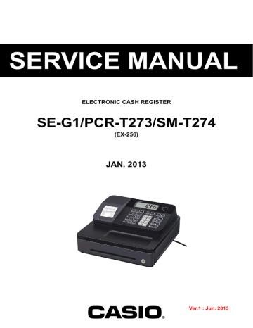
This guide explores the Casio PCR-T273 cash register, a reliable and user-friendly model ideal for small to medium-sized businesses․ It offers features such as automatic tax computation and a high-speed thermal printer․ The manual provides detailed instructions for setup, operation, and troubleshooting․

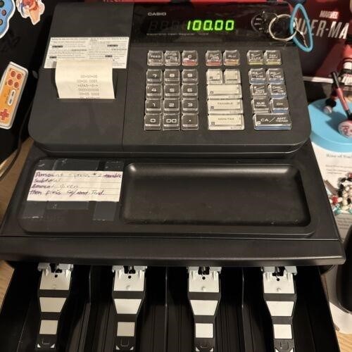
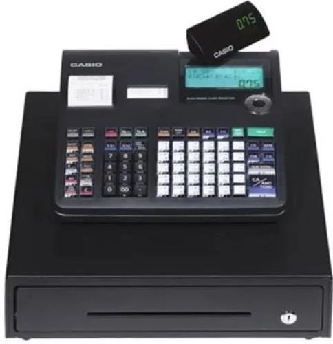
The Casio PCR-T273 is a compact, single-tape thermal cash register designed for ease of use and efficient operation in various retail and hospitality settings․ Its functionality caters to small and medium-sized businesses seeking a reliable and affordable cash management solution․ Key features include automatic tax calculation, simplifying sales transactions and reducing manual errors․ The PCR-T273 boasts a high-speed thermal printer, ensuring quick receipt generation even during peak business hours․ A user-friendly interface and clear display make operation straightforward, even for staff with limited experience․ The integrated cash drawer provides secure storage for cash and coins․ This manual details its setup, operation, maintenance, and troubleshooting․

Key Features and Functionality

The Casio PCR-T273 offers a range of features designed for efficient point-of-sale operations․ Its core functionality centers around a high-speed single-station thermal printer, producing clear and legible receipts quickly․ A bright operator display provides clear visibility of transaction details, while a customer display keeps patrons informed․ The register incorporates automatic tax computation, streamlining the checkout process and minimizing the risk of errors․ A secure locking cash drawer with designated compartments for bills and coins ensures safe cash handling․ The PCR-T273 also allows for customization of the receipt header, enabling businesses to add their logo or contact information․ Its compact design makes it suitable for various counter setups, while its durable construction ensures long-term reliability․

Setup and Initial Configuration

Setting up your Casio PCR-T273 involves several straightforward steps․ Begin by unpacking the cash register carefully and ensuring all components are present․ Connect the power cord to the register and a suitable power outlet; avoid overloading the outlet․ Before plugging in, complete the initial programming steps detailed in the manual’s quick start guide․ This usually involves setting the date, time, tax rates, and other essential operational parameters․ Refer to the user manual for specific instructions on accessing the programming mode and inputting the required data․ The manual provides clear guidance on configuring various settings, including the receipt header message․ Once the initial configuration is complete, test the functionality by processing a sample transaction to verify everything operates correctly․ Remember to consult the manual if you encounter any difficulties during the setup process․

Accessing the Casio PCR-T273 Manual

Finding the Casio PCR-T273 manual is easy․ Numerous online resources offer the user manual as a downloadable PDF․ Alternatively, contact Casio support for assistance locating the document․

Locating the Online Manual

The Casio PCR-T273 manual is readily available online through various sources․ A simple web search using keywords like “Casio PCR-T273 manual PDF” will yield multiple results․ Many websites specialize in hosting user manuals for various electronic devices, including Casio products․ These sites often categorize manuals by product type and brand, making it easy to find the specific document you need․ Be cautious when selecting a source, ensuring it’s a reputable website to avoid downloading corrupted or incorrect files․ Check for reviews or feedback from other users to verify the authenticity and quality of the provided manual․ Remember to always download from secure and trusted sources to protect your device from potential malware․ Official Casio support websites may also provide links to the manual, guaranteeing authenticity․ Exploring these options will ensure you access the correct and up-to-date version of your Casio PCR-T273 manual․

Downloading the PDF Manual

Once you’ve located a reliable source for the Casio PCR-T273 manual online, the download process is typically straightforward․ Most websites offering manuals provide a direct download link, usually a button or hyperlink labeled “Download PDF” or similar․ Clicking this link will initiate the download, saving the manual as a PDF file to your computer․ The download time will depend on your internet connection speed and the file size of the manual; the provided text mentions sizes ranging from 5․44MB to 7MB․ Ensure you have sufficient storage space available before initiating the download․ After the download completes, you can locate the file in your designated download folder or the location specified during the download process․ It’s advisable to verify the file integrity after downloading to ensure it’s not corrupted․ Opening the PDF file requires a PDF reader application, such as Adobe Acrobat Reader, which is freely available if you don’t already have one installed․ Once opened, you can navigate through the manual using the reader’s built-in tools․

Manual Contents and Navigation

The Casio PCR-T273 manual typically includes comprehensive instructions covering various aspects of the cash register’s operation․ Expect sections detailing setup and initial configuration, explaining how to program tax rates, plugging in the power cord, and customizing receipt headers․ Detailed explanations of operational procedures, including how to process sales transactions, handle returns, and utilize other functions, are also commonly included․ Troubleshooting guides address common issues and provide solutions to help resolve problems quickly․ A section dedicated to cleaning and maintenance instructions ensures the longevity of your cash register․ Furthermore, the manual may contain warranty information, contact details for Casio support, and potentially information on third-party repair services․ Navigation within the manual is usually straightforward, often with a clear table of contents, allowing for easy access to specific sections․ Page numbering and well-defined headings and subheadings facilitate quick referencing of information․ Many manuals also include helpful diagrams and illustrations to clarify complex procedures or technical specifications․

Troubleshooting and Maintenance

The Casio PCR-T273 manual offers guidance on resolving common operational issues, performing routine cleaning, and understanding warranty details for your cash register․

Common Issues and Solutions

The Casio PCR-T273 manual addresses various troubleshooting scenarios․ Paper jams are a frequent concern; the manual details how to clear the jam safely and efficiently, ensuring minimal downtime․ Problems with the thermal printer, such as blurry or faded receipts, are also covered, often attributed to low-quality paper or incorrect settings․ The manual guides users through adjusting printer settings and selecting appropriate paper rolls for optimal print quality․ Issues with the cash drawer mechanism, such as failure to open or close properly, are addressed, often pointing to simple fixes like checking for obstructions or adjusting the drawer’s alignment․ Furthermore, the manual provides solutions for error codes that might appear on the display, offering clear explanations and step-by-step instructions for rectification․ Understanding these common problems and their solutions helps maintain the smooth operation of your Casio PCR-T273 cash register․

Cleaning and Care Instructions

Regular cleaning is crucial for maintaining the Casio PCR-T273’s performance and longevity․ The manual emphasizes using a soft, slightly damp cloth to wipe the exterior surfaces, avoiding harsh chemicals or abrasive cleaners that could damage the finish․ Specific attention should be paid to the keyboard and display, gently removing any dust or debris․ For stubborn stains, a mild detergent solution can be used sparingly, followed by thorough rinsing with clean water and complete drying․ The manual also provides instructions for cleaning the receipt printer mechanism․ This involves carefully removing any paper scraps or dust from the print head and surrounding areas using a soft brush or compressed air․ Never use excessive force or liquids directly on the print head, as this could cause damage․ Proper cleaning and care will extend the life of your Casio PCR-T273 and ensure its continued reliable operation․ Regular maintenance, as outlined in the manual, helps prevent malfunctions and preserves the machine’s overall condition․

Warranty Information

The Casio PCR-T273 cash register typically comes with a limited warranty, the specifics of which are detailed within the provided user manual․ This warranty covers defects in materials and workmanship under normal use and conditions for a specified period (often one year)․ The manual will clearly outline what is and is not covered under the warranty․ This may include parts, labor, or both․ Exclusions frequently cite damage caused by misuse, accidents, or unauthorized repairs․ To claim warranty service, you’ll likely need to provide proof of purchase and follow the procedures described in the manual․ Contacting Casio’s customer support or an authorized service center is usually the first step in initiating a warranty claim․ Remember to retain your proof of purchase and the manual itself as important documentation for warranty purposes․ Understanding the warranty’s terms and conditions is essential for protecting your investment and ensures you receive the appropriate service should issues arise during the warranty period․

Additional Resources and Support

Beyond the manual, Casio offers various support avenues․ Contact their customer service, explore online forums, or utilize third-party repair services for assistance with your PCR-T273․

Contacting Casio Support

If you require assistance beyond the information provided in the Casio PCR-T273 manual, contacting Casio’s support team directly is recommended․ Their website likely provides contact details, including phone numbers and email addresses for technical support․ You may find FAQs or troubleshooting guides online as well․ When contacting support, be prepared to provide your cash register’s serial number and a clear description of the issue you are encountering․ This will help expedite the resolution process․ Casio’s support staff can provide guidance on various aspects of the PCR-T273, from initial setup and configuration to advanced programming and troubleshooting complex problems․ Remember to check Casio’s website for the most up-to-date contact information and support resources․ Utilizing their official channels ensures you receive accurate and timely assistance from trained professionals familiar with the PCR-T273’s specifications and functionality․

Online Forums and Communities

Supplementing the official Casio PCR-T273 manual, online forums and communities dedicated to cash registers or Casio products can be invaluable resources․ These platforms often host discussions among users, sharing their experiences, troubleshooting tips, and workarounds for common issues․ Participating in these forums can provide access to a wealth of collective knowledge, potentially saving time and effort in resolving problems․ Searching for relevant forums using keywords like “Casio PCR-T273,” “cash register troubleshooting,” or “point-of-sale systems” will yield numerous results․ Remember to be respectful and follow community guidelines when posting or interacting within these online spaces․ Before posting a question, search existing threads to see if your issue has already been addressed․ Engaging with these communities offers a collaborative approach to problem-solving, often leading to quick and effective solutions beyond the scope of the official manual․

Third-Party Repair Services

While Casio offers official support and repair services, exploring third-party repair options for your Casio PCR-T273 cash register can be beneficial, especially if dealing with urgent repairs or geographical limitations․ Independent repair shops specializing in electronic point-of-sale systems often possess extensive experience across various brands and models, potentially offering faster turnaround times or more competitive pricing․ Online directories and local business listings can help identify reputable third-party repair services in your area․ Before engaging with any third-party provider, ensure they have the necessary expertise and experience to repair the specific model of your cash register․ Check online reviews and testimonials to gauge their reputation and customer satisfaction levels․ Inquire about their warranty policies and repair costs upfront․ While using a third-party service might void any remaining manufacturer’s warranty, it could offer a faster and potentially more affordable solution compared to dealing directly with Casio, depending on the nature of the repair and availability of parts․

Open post

panasonic rf b40 service manual pdf

Panasonic RF-B40 Service Manual PDF⁚ A Comprehensive Guide

This guide provides essential information for servicing the Panasonic RF-B40 multi-band radio. Find troubleshooting steps, schematic diagrams, parts lists, and disassembly instructions. Learn how to repair specific components and maintain optimal performance. Access reliable online resources and community support.

The Panasonic RF-B40 is a vintage multi-band portable radio renowned for its robust build quality and impressive reception capabilities, despite its compact size. Manufactured by Panasonic (formerly Matsushita), it’s a sought-after model among shortwave radio enthusiasts and collectors. This receiver boasts a frequency coverage encompassing longwave (LW), mediumwave (MW), shortwave (SW), and FM broadcast bands, making it versatile for various listening needs. Its design, typical of its era, features a durable casing and a straightforward user interface. While specific production dates aren’t readily available in all sources, its design suggests a manufacturing period likely within the late 1980s or early 1990s. The RF-B40’s popularity stems from its ability to receive various signal types, its relatively compact and portable design, and its generally reliable performance. Many users appreciate its sensitivity and selectivity, although some online discussions point to limitations in bandwidth filtering and synchronization compared to more modern receivers. Understanding its internal workings is key to effective troubleshooting and repair, making a service manual an invaluable asset for owners. The availability of a service manual is crucial for anyone undertaking repairs or maintenance of this classic radio.

Key Features and Specifications of the RF-B40

The Panasonic RF-B40 is a portable multi-band receiver covering a wide range of frequencies. Key features include its ability to receive longwave (LW), mediumwave (MW), shortwave (SW), and FM broadcasts. While precise specifications vary depending on the source, it generally tunes from approximately 146-288 kHz (LW), 520-1610 kHz (MW), 1615-29995 kHz (SW), and 87.5-108 MHz (FM). The radio likely employs a PLL (Phase-Locked Loop) synthesized tuning system, offering precise frequency selection and stability. Its sensitivity and selectivity are generally well-regarded, allowing for clear reception even in challenging conditions, although some users note limitations in bandwidth filtering compared to more advanced models. The audio output is typically described as satisfactory for its size and era, although specific audio power output figures are not consistently reported across various online resources. Physical dimensions and weight are not consistently detailed across various online sources, suggesting variations may exist between different batches or revisions of the model. The RF-B40’s construction is usually characterized as robust and durable, reflecting the quality associated with Panasonic’s electronics. Further detailed specifications, such as antenna impedance or power consumption figures, would require referring to a dedicated service manual or original documentation.

Finding the Service Manual Online⁚ Reliable Sources

Securing a Panasonic RF-B40 service manual PDF online can be challenging, as official sources may not readily provide them. However, several avenues exist for locating this crucial document. Online marketplaces like eBay sometimes list manuals for sale, either as physical copies or digital downloads. Exercise caution and verify seller reputation before purchasing. Forums and online communities dedicated to vintage electronics or shortwave radio enthusiasts are valuable resources. Members often share links to manuals or offer assistance in locating them. Websites specializing in vintage electronics documentation might also host the manual or related information. These sites often compile user manuals, service manuals, and schematics from various manufacturers. Searching using specific keywords such as “Panasonic RF-B40 service manual PDF,” “Panasonic RF-B40 schematic,” or “Panasonic RF-B40 repair manual” can improve search results. Remember to check multiple sources, as availability can fluctuate. Always be wary of potentially fraudulent websites or sources offering questionable downloads. Be cautious of files that seem unusually large or lack credible provenance. Consider contacting Panasonic directly, though the likelihood of finding the service manual through their official channels may be low, due to the age of the device. Remember, a thorough search across multiple platforms may be required to locate the desired document.

Troubleshooting Common RF-B40 Issues

The Panasonic RF-B40, while robust, can experience common issues. No sound is a frequent problem; check the volume control, antenna connection, and power source. A faulty speaker or audio amplifier could also be the culprit. Weak reception might indicate antenna problems, poor ground connection, or interference. Ensure the antenna is fully extended and properly connected. Try different locations to minimize interference. Static or noisy audio could stem from poor antenna grounding, nearby electrical devices, or a problem within the radio’s tuning circuitry. Intermittent operation suggests potential issues with power switches, batteries (if applicable), or internal connections. Inspect the power switch for damage or poor contact. If using batteries, ensure they’re fresh and correctly installed. A malfunctioning tuner could lead to difficulty tuning stations or inconsistent reception. This often requires more in-depth troubleshooting and possibly component-level repair. Inability to receive certain bands might point to a problem with the specific band’s circuitry. This often necessitates careful examination of the radio’s internal components and potentially requires specialized knowledge or tools. Refer to a service manual for detailed troubleshooting guidance on these and other issues. Remember to always disconnect power before internal inspection or repair. Always prioritize safety and consult a qualified technician if unsure about any repair procedure.

Disassembly and Reassembly Procedures

Disassembling and reassembling the Panasonic RF-B40 requires careful attention to detail and the use of appropriate tools. Begin by disconnecting the power source to prevent electrical shock. Carefully remove the external casing, typically involving screws located on the back or bottom. Note the location and order of all screws and components for easy reassembly. Once the casing is removed, carefully examine the internal components. Take photos or make detailed notes of the wiring and component placement to aid in reassembly. When disconnecting any wires or components, do so gently to avoid damage to the delicate solder joints. Use the appropriate tools, such as a small Phillips head screwdriver and possibly a soldering iron if any components need to be desoldered. During reassembly, ensure that all components are correctly aligned and securely connected. Check all wiring connections to prevent short circuits or improper functionality. Once all internal components are securely in place, carefully reattach the external casing, ensuring all screws are properly tightened. After reassembly, test the radio thoroughly to ensure all functions are working correctly. If any problems persist, double-check all connections and consult a service manual for detailed guidance. Improper disassembly or reassembly can damage the radio; proceed with caution and consult a service manual for specific instructions if available. Remember, safety is paramount; disconnect the power before any internal work.

Schematic Diagrams and Component Identification

Understanding the schematic diagrams within the Panasonic RF-B40 service manual is crucial for effective troubleshooting and repair. These diagrams visually represent the internal circuitry, showing the interconnection of various components like transistors, resistors, capacitors, and integrated circuits. Each component is usually identified by a unique reference designator, allowing for easy cross-referencing with parts lists and component datasheets. By carefully studying the schematic, you can trace signal paths, identify potential points of failure, and understand the overall functionality of different sections of the radio. The schematic will typically include detailed information about the power supply, RF amplifier stages, intermediate frequency (IF) stages, audio amplifier, and other critical sections. Identifying components correctly is essential. The service manual may include a component list with values and descriptions. Compare the visual appearance of components on the circuit board to their representations in the schematic. Pay attention to component markings, which often indicate values or other critical information. Using a multimeter to measure component values can help verify their integrity and identify faulty parts. Accurate component identification using the schematic is essential for successful repairs and avoids incorrect replacements that could worsen the problem or cause further damage. Refer to the service manual for detailed interpretations of the schematic and component markings.

Parts Lists and Sourcing Replacement Components

The Panasonic RF-B40 service manual includes a comprehensive parts list, a vital resource for identifying and sourcing replacement components. This list typically details each component’s reference designator, value, and description, enabling efficient identification of faulty parts during troubleshooting. The manual might also specify the component’s manufacturer and part number, facilitating ordering replacements from electronics suppliers. However, finding exact replacements for older components can be challenging; some parts may be obsolete. In such cases, the service manual might suggest suitable substitutes with similar specifications. Online electronics retailers are a primary source for finding replacements. Websites specializing in electronic components often have vast databases, allowing searches by part number, value, or description. Local electronics stores might also stock common components, although the availability of specialized parts for older equipment may be limited. When sourcing substitutes, ensure that the replacement components’ specifications closely match the originals to maintain the radio’s functionality and prevent unexpected issues. It’s also advisable to check component datasheets for detailed information before installation. Accurate identification and sourcing of replacement components are essential to ensure successful repairs and the long-term operation of your Panasonic RF-B40.

Wiring Diagrams and Connections

A crucial section within the Panasonic RF-B40 service manual is dedicated to wiring diagrams. These detailed visual representations illustrate the intricate connections between the radio’s various components, providing a roadmap for understanding the signal flow and power distribution within the device. The diagrams typically use color-coded lines to represent different circuits, making it easier to trace signals and identify potential points of failure. Understanding these diagrams is vital for diagnosing and repairing faults. For instance, a wiring diagram can help identify a broken connection or a short circuit by visually tracing the path of a particular signal. The diagrams often show the interconnection of the radio’s internal components such as the tuner, amplifier, and speaker, along with external connections like the antenna and power input. These diagrams are not merely visual aids; they are essential tools for tracing signals and power pathways. By carefully studying the wiring diagrams, technicians can pinpoint the location of a malfunction and perform the necessary repairs. The accurate interpretation and use of these diagrams are indispensable for anyone undertaking repairs or modifications to the Panasonic RF-B40. The clarity and detail of these diagrams directly impact the efficiency and success of any troubleshooting and repair efforts.

Advanced Troubleshooting Techniques

The Panasonic RF-B40 service manual may include advanced troubleshooting techniques beyond basic checks. These techniques often involve using specialized test equipment like oscilloscopes or signal generators to pinpoint intermittent faults or subtle signal degradation. For example, an oscilloscope can display the waveform of a signal, revealing distortions or anomalies indicative of component failure. Signal generators allow technicians to inject test signals into the circuit to check the response of various components and stages. The manual might describe how to perform these advanced tests, including proper settings and interpretation of the results. Furthermore, the manual may detail techniques for isolating problems in complex circuits, such as using signal tracing methods to follow the path of a signal through multiple components. These methods might involve using probes to measure voltage levels at various points in the circuit. Advanced troubleshooting might also address issues related to specific components, such as the radio’s tuner or amplifier, providing detailed instructions for checking alignment or replacing internal components. The section could cover diagnosing issues related to poor selectivity, sensitivity, or audio distortion using more sophisticated methods than basic component checks. These advanced techniques require a more in-depth understanding of electronics and the use of specialized equipment, but they are essential for resolving complex problems in the RF-B40.

Calibration and Adjustment Procedures

The Panasonic RF-B40 service manual likely details calibration and adjustment procedures crucial for optimal performance. These procedures often involve fine-tuning various circuits within the radio to ensure proper operation across all frequency bands. For instance, the manual might guide you through aligning the radio’s intermediate frequency (IF) stages, a critical step in achieving optimal selectivity and sensitivity. This typically involves using specialized test equipment to measure and adjust the response of the IF filters. Calibration might also encompass adjusting the radio’s oscillator circuits to ensure accurate frequency generation and stability across the tuning range. This is particularly important for shortwave reception, where precise frequency control is essential. The manual may detail procedures for adjusting various potentiometers or trimmer capacitors to fine-tune the performance of specific circuits, such as the audio amplifier or the automatic gain control (AGC) system. These adjustments might require specialized test equipment and a thorough understanding of the radio’s circuitry. Furthermore, the manual could contain instructions for calibrating the radio’s meter, if equipped, to ensure accurate readings of signal strength or other parameters. Proper calibration is critical for restoring or maintaining the RF-B40’s performance to factory specifications and ensuring accurate and reliable reception across all frequency bands. Failure to properly calibrate the radio can result in poor performance, including reduced sensitivity, inaccurate frequency response, or distorted audio.

Repairing Specific Components (e.g., Tuners, Amplifiers)

The Panasonic RF-B40 service manual should offer detailed guidance on repairing specific components. This could involve troubleshooting and replacing faulty transistors, integrated circuits, resistors, or capacitors within the tuner section. The manual may provide schematics and diagrams illustrating the connections and relationships between these components, aiding in diagnosing malfunctions. For example, if the radio exhibits poor frequency response or selectivity, the manual might direct you to inspect and potentially replace components within the radio frequency (RF) amplifier or mixer stages of the tuner. Similarly, if the audio output is weak or distorted, the service manual will guide you through inspecting the audio amplifier circuit. This could include checking for faulty transistors, damaged output capacitors, or issues with the volume control potentiometer. The process might involve testing individual components using a multimeter to identify faulty parts before attempting replacements. The manual might also include information on replacing or repairing other vital components like the power supply, ensuring safe and correct voltage levels for all parts of the radio. Remember, working with electronics requires caution. Improper handling can lead to further damage or even injury. Always disconnect the power before undertaking any repairs and take necessary precautions when handling potentially charged components. The detailed instructions and diagrams within the service manual are crucial for successfully repairing the RF-B40’s internal components.

Alternative Resources and Communities

Maintaining Your RF-B40 for Optimal Performance

Proper maintenance is key to prolonging the life and performance of your Panasonic RF-B40. The service manual might recommend regular cleaning, focusing on the external casing and controls. Dust accumulation can affect the radio’s operation and aesthetics; gentle cleaning with a soft, dry cloth is usually sufficient. Avoid using harsh chemicals or abrasive materials. For more stubborn grime, a slightly damp cloth may be used, ensuring it is thoroughly dried afterward to prevent moisture damage. Internal maintenance, while more complex, is also important, although it may necessitate specialized tools and knowledge. The service manual might detail procedures for checking and cleaning internal components, such as the tuning mechanism or antenna connections. Loose connections or corroded contacts can lead to reduced performance or signal reception. Any cleaning or adjustments should be performed with care, following the instructions in the manual precisely. Regularly inspect the antenna for any damage or bending. A damaged antenna will significantly impair reception quality. Storage also plays a crucial role. Store the RF-B40 in a cool, dry place, away from direct sunlight and extreme temperatures. Avoid storing it in humid environments, as moisture can cause corrosion and damage internal components. If you’re not using the radio for an extended period, consider removing the batteries to prevent leakage, a common cause of internal damage. Following these simple maintenance guidelines will help you keep your Panasonic RF-B40 functioning optimally for many years.

Open post

brother p touch d200 manual

Brother PT-D200 Manual⁚ A Comprehensive Guide

This guide provides a complete overview of the Brother PT-D200 P-touch label maker; Learn how to download the manual, create custom labels, select tapes, troubleshoot issues, and more. Master your PT-D200 for all your labeling needs. Safety precautions and maintenance tips are also included.

Downloading the Brother PT-D200 Manual

Obtaining the Brother PT-D200 manual is straightforward. Numerous online resources offer the user manual as a downloadable PDF. Several websites, including Brother’s official support pages and third-party sites specializing in manuals and downloads, provide direct links to the document. The file size typically ranges from several megabytes to over 10MB depending on the version and language. Ensure you download from a reputable source to avoid malware. The file format is consistently PDF, compatible with most operating systems and devices using a PDF reader like Adobe Acrobat Reader (available for free download if needed).

Before downloading, check the manual’s details for version number and language to ensure compatibility with your label maker and personal preferences. Some sites may offer multiple versions reflecting updates or regional variations. The download process usually involves clicking a link, confirming the download, and saving the file to a location on your computer or device where you can easily access it. Once downloaded, open the PDF to access the complete instruction manual for the Brother PT-D200.

Available Manual Versions and Languages

The Brother PT-D200 manual is available in various versions and languages to cater to a global audience. While the core content remains consistent across versions, updates may address new features, bug fixes, or improved clarity. Checking the version number is crucial to ensure you have the most up-to-date instructions. Older versions might lack information on recent software updates or accessories. The version number is often indicated in the filename or within the document itself.

Language support varies depending on the region and the source of the download. Commonly available languages include English (with regional variations such as US English, UK English, Canadian English, and Australian English), French, Spanish, German, and Japanese. However, the availability of specific languages might be limited. When downloading, carefully check the language options to select the one that best suits your needs. If your preferred language is unavailable, contacting Brother’s support might provide alternative solutions or point you to translated versions from other user communities.

Manual File Size and Format

The Brother PT-D200 manual is typically provided in PDF (Portable Document Format) for consistent viewing across different operating systems and devices. PDFs offer advantages like searchability, easy navigation with bookmarks, and the ability to print specific sections. However, the file size can vary depending on the version and included content, ranging from a few megabytes to over 15 MB. Larger files often include more comprehensive information, high-resolution images, or multiple language versions. Before downloading, ensure you have sufficient storage space on your device.

Consider your internet connection speed when downloading. Larger files require more time to download, especially with slower connections. If you encounter difficulties downloading, check your internet connection and try again later. Alternatively, you can contact Brother support for assistance or inquire about alternative download methods. Remember, the file size is listed before initiating the download, allowing you to make an informed decision about proceeding. While a smaller file size might seem more convenient, ensure it contains the necessary information before settling for a potentially incomplete manual.

Accessing Brother’s Support Line

If you require assistance beyond the information provided in the Brother PT-D200 manual, Brother offers various support channels to help you troubleshoot problems or answer any questions you may have regarding your label maker. One primary method is accessing their support line via phone. The provided number, 877-276-8437, connects you directly to Brother’s P-touch support team. Representatives are available to assist with technical issues, software questions, or any other inquiries you may have concerning the operation or maintenance of your PT-D200.

Before calling, gather pertinent information, such as your product’s serial number, the specific issue you are facing, and the steps you have already taken to troubleshoot the problem. This will help streamline the support process and ensure a quicker resolution. Keep in mind that call wait times might vary depending on the time of day and call volume. Alternatively, Brother offers online support resources, including FAQs, troubleshooting guides, and downloadable manuals. These resources can often provide quick solutions to common problems. Exploring these options before calling can save you time and potentially resolve the issue independently.

Using the Brother PT-D200 Label Maker

The Brother PT-D200 is a user-friendly label maker designed for ease of operation. Begin by installing the necessary batteries or connecting the AC adapter (AD-24ES). Insert a Brother TZe tape cassette, ensuring it’s correctly aligned and the tape feeds under the cutter. Close the cassette cover securely. The PT-D200’s intuitive interface allows for easy label creation. Input your desired text using the keypad, selecting from various fonts, styles, and sizes. Experiment with the available frames and character options to customize your labels.

The device offers a preview function so you can see what your label will look like before printing. This allows for corrections and adjustments before committing to printing. The PT-D200 has features like chain printing for multiple labels and adjustable label lengths. Once your label is designed, simply press the print button. The built-in cutter neatly trims your label after printing. Always remember to refer to the complete manual for detailed instructions and advanced features. Proper handling and maintenance, as outlined in the manual, will ensure your PT-D200 provides long-lasting reliable service.

Creating Custom Labels with the PT-D200

The Brother PT-D200 empowers you to design personalized labels with ease. Begin by selecting your desired tape cartridge, considering both width and color options to match your needs. The device supports various tape widths, offering flexibility for different applications. Once your tape is loaded, navigate through the intuitive menu system to input your text. The PT-D200’s display shows a preview of your label, allowing adjustments before printing. You can customize your labels with different font styles, sizes, and even add frames or decorative elements.

For more complex designs, explore the available formatting options. Experiment with character spacing, alignment, and other settings to create visually appealing labels. The PT-D200 allows you to incorporate numbers and symbols, enhancing the informational content. Remember to check the maximum character count per line to avoid truncation. If creating multiple identical labels, the chain print function significantly streamlines your workflow. The ability to adjust the label length caters to various needs. Before printing, carefully review your label design on the preview screen to ensure accuracy. With practice, you’ll master the art of creating professional-looking, custom labels with your PT-D200.

Selecting Tape Cartridges and Their Specifications

Choosing the right Brother TZe tape cartridge is crucial for optimal performance and label quality with your PT-D200. Brother offers a wide variety of TZe tapes, each with unique specifications to suit diverse applications. Key considerations include tape width, color, and material. Tape widths typically range from 3.5mm to 12mm, allowing you to create labels of various sizes for different uses, from small identifying labels to larger address labels. The color selection is extensive, offering options from standard black on white to a wide range of colors, including fluorescent and metallic tapes for enhanced visibility or aesthetics. The material also plays a significant role; consider the environment where your label will be used.

Laminated tapes provide superior durability and resistance to abrasion, chemicals, and extreme temperatures, making them ideal for outdoor or harsh environments. For indoor use, standard matte or glossy tapes offer a more budget-friendly option. Before purchasing, check the compatibility of the TZe tape with your PT-D200 model. The tape cartridge packaging clearly indicates the compatible printer models. Incorrect tape selection may lead to printing issues or damage to your label maker. Always refer to the Brother website or the user manual for a comprehensive list of compatible TZe tapes and their detailed specifications, ensuring you choose the perfect tape for your labeling task. Prioritize quality and compatibility for seamless label creation.

Troubleshooting Common PT-D200 Issues

Encountering problems with your Brother PT-D200 label maker is frustrating, but many common issues have straightforward solutions. If your PT-D200 isn’t printing, first check if the tape cassette is correctly installed and contains tape. Ensure the power is on and the batteries are fresh or the AC adapter is properly connected. A low battery indicator might appear; replace or recharge batteries as needed. If the print is faint or blurry, consider replacing the tape cartridge. Old or damaged tape can lead to poor print quality. Make sure you’re using Brother TZe tapes specifically designed for the PT-D200; incompatible tapes won’t print correctly. Check for any obstructions in the tape path; a jammed tape can prevent printing. If the tape is jammed, carefully remove it following the instructions in your manual, ensuring you don’t damage the print head.

If the LCD screen displays error messages, refer to the troubleshooting section of your user manual for specific guidance. Common error messages often indicate low batteries, incorrect tape installation, or other simple problems. If you continue to experience difficulties after trying these steps, contacting Brother’s support line can be helpful. Their technicians can provide further assistance and guide you through more complex troubleshooting steps. Remember to note the error messages displayed on the screen before calling, as this information will aid in faster and more efficient problem resolution. Proactive maintenance, such as regularly cleaning the print head, can prevent many issues and ensure the longevity of your PT-D200 label maker.

Battery Installation and Usage

The Brother PT-D200 operates using six AAA alkaline batteries (LR03) or six rechargeable Ni-MH batteries (HR03). To install batteries, open the battery compartment cover, typically located on the back or bottom of the device. Insert the batteries, ensuring correct polarity (+ and -). The manual clearly illustrates the correct orientation. Always replace all six batteries simultaneously for optimal performance and to prevent inconsistencies. Brother recommends using fresh, high-quality batteries to ensure reliable operation. Avoid mixing old and new batteries, or different types of batteries, as this can lead to reduced performance or even damage to the device. Low battery power might manifest as faint printing, slow operation, or error messages on the LCD screen. The PT-D200 does not have a built-in charging mechanism for rechargeable batteries; you’ll need a separate AAA Ni-MH charger.

When using rechargeable Ni-MH batteries, ensure they are fully charged before use. The operational lifespan of batteries varies based on usage intensity and battery type. Always disconnect the batteries when the device is not in use, especially for extended periods, to conserve battery life and prevent potential leakage. If battery fluid leaks, take immediate precautions. Avoid touching leaked fluid; if contact occurs, rinse thoroughly with clean water and seek medical attention if irritation persists. Never dispose of batteries in fire; follow local regulations for proper battery disposal. Remember to consult the Brother PT-D200 manual for the most accurate and up-to-date instructions regarding battery usage, installation, and safety precautions specific to your model.

Powering the PT-D200 with the AC Adapter

While the Brother PT-D200 operates primarily on battery power, it also offers the convenience of AC adapter operation. This eliminates the need for frequent battery changes, particularly beneficial for extended labeling tasks. The recommended AC adapter for the PT-D200 is the Brother AD-24ES. Using a different adapter may void the warranty and potentially damage the device. Before connecting the AC adapter, ensure the PT-D200 is switched off to prevent electrical surges. Locate the DC input port on the label maker; this is usually clearly marked in the manual. Firmly plug the AC adapter into this port, ensuring a secure connection. Then, plug the adapter’s power cord into a suitable wall outlet. The label maker should now be powered by the AC adapter.

While using the AC adapter, you can still use the battery compartment, but it is not necessary. The AC adapter will provide the primary power source. However, if there’s a power outage, the device will automatically switch to battery power if batteries are installed. Always ensure the AC adapter and power cord are free from damage before use; avoid bending or twisting the cord excessively. If you notice any damage, discontinue use immediately and contact Brother support. Never use the PT-D200 with a damaged AC adapter, as this could pose a safety risk. Refer to the Brother PT-D200 user manual for detailed instructions and safety precautions concerning the use of the AC adapter. Proper use of the AC adapter ensures optimal performance and extends the lifespan of your PT-D200 label maker.

Safety Precautions and Warnings

Operating the Brother PT-D200 safely is paramount. Never use the device during a lightning storm; this could damage the internal components and pose a shock hazard. Avoid using the label maker in excessively humid environments or locations with extreme temperatures, as this can affect its performance and longevity. Always use the specified voltage and the suggested AC adapter (AD-24ES) to prevent damage or failure. Never attempt to disassemble or modify the PT-D200, the AC adapter, or the batteries; doing so voids the warranty and may lead to injury. Exercise caution when handling batteries to prevent accidental ingestion, especially around children. If a battery is swallowed, immediately seek medical attention. Avoid touching the print head immediately after printing to prevent burns.

Always replace all six batteries simultaneously with new batteries of the same type and manufacturer. Mixing old and new batteries or different types can lead to malfunctions and potentially damage the device. Never use a damaged or leaking battery. If battery fluid comes into contact with skin or clothing, rinse immediately with plenty of clean water and seek medical attention if necessary. Dispose of used batteries properly according to local regulations. Do not expose the device to direct sunlight or rain. Keep the PT-D200 out of reach of children. Never use sharp objects to change batteries; this can lead to damage or injury. Always disconnect the AC adapter and remove batteries before cleaning or performing maintenance. Consult the complete user manual for detailed safety instructions and warnings to ensure safe operation of your Brother PT-D200.

FCC Compliance Information

The Brother PT-D200 label maker complies with Part 15 of the FCC Rules. Operation is subject to the following two conditions⁚ (1) This device may not cause harmful interference, and (2) this device must accept any interference received, including interference that may cause undesired operation. This equipment has been tested and found to comply with the limits for a Class B digital device, pursuant to Part 15 of the FCC Rules. These limits are designed to provide reasonable protection against harmful interference in a residential installation. This equipment generates, uses, and can radiate radio frequency energy and, if not installed and used in accordance with the instructions, may cause harmful interference to radio communications.

However, there is no guarantee that interference will not occur in a particular installation. If this equipment does cause harmful interference to radio or television reception, which can be determined by turning the equipment off and on, the user is encouraged to try to correct the interference by one or more of the following measures⁚ Reorient or relocate the receiving antenna. Increase the separation between the equipment and receiver. Connect the equipment into an outlet on a circuit different from that to which the receiver is connected. Consult the dealer or an experienced radio/TV technician for help. Changes or modifications not expressly approved by Brother Industries, Ltd. could void the user’s authority to operate the equipment. Remember to always refer to the complete user manual for the most up-to-date and comprehensive FCC compliance information for your Brother PT-D200 label maker.

Cleaning and Maintaining Your PT-D200

Regular cleaning of your Brother PT-D200 label maker will ensure optimal performance and longevity. To clean the exterior casing, use only a soft, dry cloth. Never use harsh chemicals, abrasive cleaners, or solvents such as alcohol or organic solutions, as these can damage the plastic and electronic components. Avoid getting any liquids inside the device. For stubborn marks, gently wipe with a slightly damp cloth, ensuring it’s only lightly moistened and then immediately dry the area thoroughly.

The print head requires special care. Never touch the print head directly, as this can cause damage. Instead, use a soft, dry cloth or wipe to gently clean any debris or residue from around the print head area. Avoid applying any pressure to the print head itself. If you encounter persistent issues with print quality, consider replacing the tape cartridge to rule out tape-related obstructions. Always ensure the power is turned off and the AC adapter is disconnected before cleaning. Proper maintenance, including regular cleaning, will significantly extend the life of your PT-D200 and maintain its high-quality label printing capabilities.

Open post

bmw flexible fast charger manual

BMW Flexible Fast Charger⁚ A Comprehensive Guide

This guide provides a complete overview of the BMW Flexible Fast Charger, covering its functionality, safe usage, troubleshooting, optimal charging times, adapter use, maintenance, specifications, manual access, and disposal information. It aims to equip users with the knowledge for efficient and safe charging practices.

Understanding the Charger’s Functionality

The BMW Flexible Fast Charger is a versatile Mode 2 charging cable designed for BMW, MINI, and Rolls-Royce electric vehicles. Its primary function is to charge the vehicle’s battery using either 120V or 240V household power outlets. The charger’s adaptability stems from its interchangeable adapters, allowing for compatibility with various power outlets worldwide. The charging process is initiated by connecting the charger to both the vehicle and the power source. The charger’s internal circuitry manages the charging current, ensuring safe and efficient charging within the vehicle’s specifications. LED indicators on the charger provide real-time feedback on the charging status, including charging progress, errors, and power limitations. The device also incorporates safety features to prevent overcharging, overheating, and other potential hazards. Its portability and ease of use make it a convenient solution for home charging. The user manual provides detailed instructions on its operation and troubleshooting.

Safe Charging Practices⁚ Disconnecting and Reconnecting

Before disconnecting the BMW Flexible Fast Charger, always ensure the charging process is complete and the charger has indicated a successful charging cycle. Begin by unplugging the vehicle connector from the car’s charging port, ensuring a gentle and firm grip on the connector itself to avoid damaging the port or the cable. Next, disconnect the charger’s mains adapter from the wall outlet. Never pull on the cable; instead, grasp the adapter firmly. After disconnecting, wait at least five seconds before reconnecting to allow the charger’s internal systems to reset. When reconnecting, first plug the mains adapter into a properly grounded and approved outlet. Then, firmly connect the vehicle connector to the car’s charging port. Always visually inspect both the vehicle connector and the mains adapter for any signs of damage or wear before each use. If any damage is detected, discontinue use and contact BMW customer support or an authorized service center for assistance. Regularly check the condition of the charging cable and connectors to prevent potential hazards. Adhering to these steps will ensure safe and reliable charging.

Troubleshooting Common Issues

If the BMW Flexible Fast Charger fails to initiate a charging cycle, first verify that the mains adapter is securely connected to both the charger and a functioning wall outlet. Check the outlet itself by testing it with another device. Ensure the vehicle connector is firmly attached to the car’s charging port; a loose connection can prevent charging. Examine the charger’s LED indicators for any error codes; consult the user manual for their meaning. A blinking orange light often signals a self-test failure or a relay fault, while a red light may indicate an internal error or over-temperature protection. If these checks don’t resolve the issue, try a different wall outlet. Power surges or faulty wiring in your home’s electrical system can disrupt charging. If the problem persists despite these steps, contact your BMW dealer or customer support. They can diagnose more complex issues, such as internal charger malfunctions or problems with the vehicle’s charging system. Note that the charger’s IP67 rating protects against water and dust ingress, but physical damage can still occur if mishandled. Avoid using the charger in extreme temperatures or wet conditions.

Optimal Charging Times and Electricity Costs

Optimizing charging times for your BMW electric vehicle using the Flexible Fast Charger involves understanding your electricity provider’s rate structure. Many utilities offer off-peak pricing, with lower rates during periods of lower demand, typically overnight. Charging during these off-peak hours significantly reduces the overall electricity cost. To determine the most economical charging schedule, contact your electricity supplier and inquire about their time-of-use rates. They can provide a detailed breakdown of their pricing structure, highlighting peak and off-peak hours. This information allows you to plan charging sessions strategically to minimize expenses. For example, if off-peak rates are available between 11 PM and 7 AM, initiating a charging session within this window will likely save money. The charging time required depends on factors like your battery’s state of charge, the charger’s power output (120V or 240V), and the vehicle’s battery capacity. A full charge might take several hours, while topping off the battery from 80% to 100% may only take a few hours. Always consult your vehicle’s manual for charging recommendations and avoid fully charging the battery daily to prolong its lifespan.

Using Interchangeable Adapters for Versatile Charging

The BMW Flexible Fast Charger’s versatility stems from its interchangeable adapters, enabling charging from various power outlets. This adaptability is crucial for convenient charging at home, on the road, or in different locations with varying electrical setups. The charger typically includes adapters for both 120V and 240V outlets, catering to standard household power and higher-voltage setups. Before connecting the charger, carefully identify the correct adapter for your chosen outlet. Ensure the outlet’s amperage rating is sufficient for the selected adapter and the charger’s power requirements. Improper adapter selection can lead to insufficient charging speed or even damage to the charger or electrical system. The included manual details the proper connections and adapter usage. Always inspect the adapter and cable for any signs of damage before use. Damaged components should be replaced immediately to prevent electrical hazards. When switching between adapters, ensure the previous adapter is securely disconnected before connecting the new one. This prevents accidental short circuits or damage. The ease of swapping adapters makes the BMW Flexible Fast Charger a truly convenient and portable solution for charging your BMW electric vehicle in diverse environments;

Maintaining Your Flexible Fast Charger

Regular maintenance ensures the longevity and optimal performance of your BMW Flexible Fast Charger. After each charging session, allow the charger to cool down before storing it. Avoid exposing the charger to extreme temperatures, direct sunlight, or moisture, as these conditions can damage its internal components. Periodically inspect the power cord, vehicle connector, and any adapters for signs of wear, fraying, or damage. Replace any damaged parts immediately to prevent safety hazards and maintain efficient charging. Keep the charger’s exterior clean by wiping it gently with a damp cloth. Avoid using harsh chemicals or abrasive cleaners, as these can damage the charger’s surface. Proper storage is essential; store the charger in a cool, dry place away from sharp objects or other items that could damage it. When not in use, coil the power cord neatly to prevent tangling and accidental damage. The user manual provides specific cleaning and storage recommendations. Regularly check the LED indicators on the charger to identify any potential problems or errors. If you notice any unusual behavior or error messages, consult the troubleshooting section in the user manual or contact BMW customer support. By following these simple maintenance practices, you can prolong the life of your BMW Flexible Fast Charger and ensure reliable charging for your electric vehicle.

Charger Specifications and Environmental Considerations

The BMW Flexible Fast Charger’s specifications vary depending on the model and included adapters. Key specifications typically include input voltage (120V or 240V), output current (amperage), charging power (kilowatts), and IP protection rating (indicating its resistance to dust and water ingress – often IP67 for enhanced protection). The charger’s operating temperature range is crucial; it usually operates within a wide temperature range but extreme temperatures can affect performance. Consult your user manual for precise specifications for your specific charger model. Environmental considerations are equally important. The charger’s manufacturing process and materials are designed to minimize environmental impact. However, responsible disposal is vital at the end of the charger’s lifespan. Do not discard the charger with regular household waste; instead, follow local regulations for the proper disposal and recycling of electronic waste. The charger is designed to meet global environmental standards and regulations. Its packaging minimizes waste materials, promoting sustainability. The efficiency of the charger contributes to reduced energy consumption during charging. By using the charger according to its specifications and disposing of it responsibly, you can contribute to environmental sustainability. Always refer to the user manual and local regulations for detailed disposal instructions.

Accessing and Downloading the User Manual

The BMW Flexible Fast Charger user manual provides essential information for safe and efficient operation. To access the manual, several options are available. Firstly, check the packaging your charger came in; the manual should be included within the box. If not, or if you require a digital copy, visit the official BMW website. Their support section usually offers downloadable manuals for various models and accessories. You may need to input your vehicle’s identification number (VIN) or search using the charger’s model number to locate the correct manual. Many third-party websites, such as ManualsLib, also host user manuals for various products, including the BMW Flexible Fast Charger. However, always verify the authenticity of such websites before downloading any documents. Be cautious of unofficial sources as incorrect information could lead to improper usage and safety hazards. Downloading from the official BMW website ensures you obtain the most accurate and up-to-date version of the user manual. Once downloaded, save the manual for future reference. Regularly review the manual to refresh your knowledge on safe operating procedures and troubleshooting common issues. The manual contains valuable information to maximize the charger’s functionality and lifespan.

Disposal and Recycling Information

Proper disposal of the BMW Flexible Fast Charger is crucial for environmental protection. This device contains electronic components and materials that require specialized recycling processes. Do not discard it in regular household waste. To ensure responsible disposal, first, disconnect the charger from both the vehicle and the power outlet. Then, carefully package the charger to prevent damage during transportation. Check with your local waste management authority or a qualified electronic waste recycling center for guidance on appropriate disposal methods in your area. Many municipalities have designated drop-off points for electronic waste, offering convenient and environmentally sound recycling options. Alternatively, some retailers may offer take-back programs for electronics, allowing you to return your old charger when purchasing a new one. Before disposing of the charger, remove any personal data from it. Consult the user manual for specific instructions on how to delete stored data safely. By properly disposing of your BMW Flexible Fast Charger, you contribute to reducing electronic waste and protecting the environment. Remember that incorrect disposal can lead to harmful environmental consequences, so it is essential to follow the proper procedures.

Open post

manual dometic rv thermostat wiring diagram

Dometic RV Thermostat Wiring⁚ A Comprehensive Guide

This guide provides a detailed overview of Dometic RV thermostat wiring, covering various configurations and troubleshooting tips. Understanding your thermostat’s wiring is crucial for proper functionality and efficient climate control in your RV. We’ll explore different wire types, color codes, and common connection diagrams to help you navigate the process successfully.

Understanding Basic Wiring Configurations

Dometic RV thermostats employ various wiring configurations depending on the model and features. The most basic setups involve three wires⁚ power (typically 12V), a common wire, and either a heating or cooling wire, allowing for simple on/off control. More advanced systems may utilize four or five wires, incorporating additional functionalities like fan speed control and auxiliary heating circuits. These additional wires often manage different aspects of the climate control system, such as selecting cooling or heating modes, adjusting fan speeds, or communicating with other components via a CANbus interface. Understanding the specific wiring diagram for your Dometic thermostat model is crucial for correct installation and operation. Incorrect wiring can lead to malfunction or even damage to the system. Always refer to the manufacturer’s wiring diagram specific to your unit before undertaking any wiring work. Pay close attention to wire colors and their corresponding functions to avoid errors. If you are unsure about any aspect of the wiring process, consult a qualified RV technician for assistance.

Three-Wire Thermostat Wiring Diagrams

Three-wire thermostat wiring diagrams represent a simplified approach to connecting your Dometic RV thermostat. This configuration typically involves a power wire (often 12V+), a common wire, and a single wire for either heating or cooling. The power wire supplies the necessary voltage to operate the thermostat. The common wire serves as a neutral return path for the electrical circuit. The remaining wire is dedicated to either activating the heating element (if present) or engaging the cooling system, depending on the selected mode. While this setup lacks the sophistication of multi-wire systems, it offers a straightforward solution for basic climate control needs. Understanding the color coding of these wires is crucial. Common color schemes include red for positive power, black or blue for common, and yellow or white for the heating or cooling circuit. However, always consult your specific thermostat’s wiring diagram to ensure accurate identification before connecting any wires. Improper connection can lead to system failure or damage. A correctly wired three-wire system will reliably switch between heating and cooling modes, allowing you to maintain a comfortable temperature within your RV.

Four-Wire and Five-Wire Thermostat Connections

Stepping up from the basic three-wire setup, four-wire and five-wire Dometic RV thermostat connections offer enhanced control and functionality. Four-wire systems typically incorporate separate wires for heating and cooling, providing independent control over each function. This allows for simultaneous operation of both heating and cooling elements when needed, offering greater flexibility in managing the RV’s climate. The addition of a dedicated fan wire in a four-wire system enables independent fan control, regardless of the heating or cooling mode. This allows for ventilation without necessarily engaging the heating or cooling elements. Five-wire systems often add a second fan wire, providing control over different fan speeds or possibly a dedicated “auto” mode. The increased number of wires necessitates careful attention to the wiring diagram specific to your model. Incorrect wiring can lead to malfunctions or damage. Common color codes often include red for power, black or blue for common, yellow for cooling, white for heating, and green or another color for the fan(s). Always refer to the manufacturer’s documentation for precise wire identification and connection guidance. These multi-wire configurations provide more sophisticated climate control compared to the simpler three-wire systems, providing better comfort and energy efficiency in your RV.

Identifying Wire Colors and Functions

Correctly identifying wire colors and their corresponding functions is paramount when working with Dometic RV thermostat wiring. While some standardization exists, variations can occur depending on the specific model and year of manufacture. Commonly, red signifies the 12V power supply, crucial for the thermostat’s operation. A white wire often designates the heating circuit, controlling the activation of the furnace or heating element. Yellow typically represents the cooling circuit, responsible for activating the air conditioning unit. A green wire often serves as a ground, providing a safety path for electrical current. However, these are not universally consistent. Some systems utilize blue for common or neutral, while others might use a brown or other color for specific functionalities such as a second fan or an auxiliary control. Furthermore, the presence of a communication wire, often labeled “comms,” is common in modern Dometic thermostats, facilitating data exchange with other RV systems. The absence or presence of an orange wire might indicate additional features or connections. Always consult the wiring diagram specific to your Dometic thermostat model, which often includes a detailed color-coded key. Misidentification can lead to system malfunctions or even damage to the equipment. Using a multimeter can help verify the function of each wire if the wiring diagram is unavailable or unclear.

Common Wire Color Codes (Red, White, Yellow, Green, Blue)

While wire color codes aren’t universally standardized across all Dometic RV thermostat models, some common conventions exist. Red frequently denotes the 12-volt power supply, essential for the thermostat’s operation. A correctly connected red wire ensures the thermostat receives the necessary voltage to function. White often signifies the heating circuit, activating the furnace or heating element within the RV’s climate control system. Yellow typically corresponds to the cooling circuit, controlling the air conditioning unit. A properly connected yellow wire ensures the AC unit receives the correct signal to start cooling. Green generally represents the ground wire, providing a safety path for electrical current. Its connection ensures proper grounding and protects against electrical shocks. Blue frequently serves as a common or neutral wire, completing the circuit and ensuring proper current flow. However, it’s crucial to remember that these are common conventions, and variations might exist depending on the specific Dometic model and even the year of manufacture. Always consult your specific thermostat’s wiring diagram for accurate color-code interpretation before attempting any wiring changes. Using a multimeter can help verify wire functions if the diagram is unclear or unavailable, preventing potential damage or system malfunctions. Always disconnect power before making any changes.

Troubleshooting Common Wiring Issues

Troubleshooting Dometic RV thermostat wiring problems often begins with a visual inspection. Loose connections are a frequent culprit, easily remedied by tightening the wire nuts or screws. A multimeter can be invaluable in testing for voltage at various points in the circuit. Confirming the presence of voltage at the thermostat’s power input (typically red wire) indicates a power supply issue elsewhere in the system. If voltage is present but the system doesn’t respond, suspect a faulty thermostat or a problem with the connected appliance (AC unit or furnace). Checking continuity between wires helps identify broken connections or faulty wiring. A lack of continuity between expected points indicates a break in the circuit. Incorrect wire connections are another common issue. Carefully compare your wiring with the provided diagram, ensuring each wire is connected to the correct terminal. If the problem persists, consider the possibility of a more complex electrical issue beyond the thermostat itself, such as a faulty control board or a problem within the HVAC system. In such cases, professional assistance might be necessary. Remember to always disconnect power before performing any checks or repairs to ensure your safety.

Dometic CCC2 Thermostat Wiring

The Dometic CCC2 thermostat presents a more advanced wiring configuration compared to simpler models. Its sophisticated design often incorporates a CANbus interface, enabling communication with other components in the RV’s system. While the specific wiring diagram will vary based on the RV’s model and year, some common aspects remain consistent. The power supply wires (typically red and black or blue for positive and negative, respectively) provide the necessary voltage. The control wires manage the communication between the thermostat and the HVAC system, dictating the desired temperature and fan speed. These wires often use different colors and sometimes include a dedicated communication wire for the CANbus system. A grounding wire (usually green) ensures proper earthing and safety. Before undertaking any wiring work, consult the specific wiring diagram for your CCC2 thermostat model. Improper connections can lead to malfunctions or damage to the system. Always double-check your wiring against the manufacturer’s instructions, ensuring correct connections to avoid electrical hazards. If you lack confidence in your electrical skills, it’s always recommended to seek professional assistance for installation and troubleshooting. Proper wiring of the Dometic CCC2 is crucial for optimal performance and safety.

Advanced Features⁚ CANbus Interface

Many modern Dometic RV thermostats, particularly the higher-end models like the CCC2, incorporate a CANbus (Controller Area Network) interface. This sophisticated communication protocol allows for seamless integration with other systems within your RV. Instead of relying on simple on/off signals, the CANbus enables complex data exchange, providing enhanced control and monitoring capabilities. This means the thermostat can communicate not only with the air conditioning unit but also potentially with other devices such as lighting systems, battery monitors, and even entertainment systems. The CANbus interface often uses a dedicated wire or set of wires for communication. These wires typically carry digital signals rather than the simple voltage levels found in traditional wiring setups. Understanding the CANbus configuration is crucial for proper installation and troubleshooting. Incorrect wiring or interference with the CANbus network can lead to system malfunctions and require advanced diagnostic tools to resolve. If you are working with a thermostat featuring CANbus communication, it is strongly recommended to refer to the manufacturer’s detailed wiring instructions and possibly seek assistance from a qualified RV technician to avoid causing damage or hindering the functionality of the RV’s integrated systems. Improper CANbus wiring can disrupt the entire network.

Installation Guidelines and Best Practices

Proper installation of your Dometic RV thermostat is crucial for optimal performance and longevity. Begin by carefully reviewing the manufacturer’s provided wiring diagram specific to your thermostat model. Ensure power to the system is disconnected before commencing any wiring work to prevent electrical shocks. Locate a suitable mounting position for the thermostat; avoid areas exposed to direct sunlight, excessive heat, or vibrations. A well-ventilated location is ideal to ensure accurate temperature readings. Neatly route the wiring, using cable ties or clips to secure wires and maintain a clean installation. Avoid sharp bends or kinks in the wiring, which can damage the wires over time. After connecting all wires according to the wiring diagram, carefully double-check each connection before restoring power; Test the thermostat’s functionality by turning it on and setting the desired temperature. Monitor the system’s performance, noting any unusual behaviors or errors. If any issues arise, refer back to the manufacturer’s troubleshooting guide or contact a qualified technician for assistance. Remember, a correctly installed thermostat will provide years of reliable service, enhancing your RV’s comfort and overall enjoyment.

Location and Mounting Considerations

Choosing the right location for your Dometic RV thermostat is critical for accurate temperature readings and user convenience. Avoid areas subjected to direct sunlight or significant heat sources like ovens or radiators, as these can skew temperature readings and potentially damage the thermostat. Similarly, avoid mounting the thermostat on exterior walls, where temperature fluctuations can be extreme. Interior walls offer better temperature stability. Consider the accessibility of the thermostat; ensure it’s easily reachable for adjustments without being in a cramped or obstructed location. For optimal functionality, mount the thermostat at a height consistent with average eye level. This ensures easy visibility and manipulation of the controls. Use appropriate mounting hardware suitable for your RV’s interior surfaces. Ensure the mounting surface is clean, dry, and stable to prevent the thermostat from becoming loose or falling. Before permanently securing the thermostat, test its functionality to verify accurate temperature readings. Proper location and mounting guarantee a user-friendly and reliable climate control experience in your RV.

Setting Temperature Differentials (d1 and d2)

Dometic RV thermostats often feature adjustable temperature differentials, typically denoted as “d1” and “d2,” allowing for fine-tuning of the climate control system’s responsiveness. These settings determine the temperature difference between the setpoint and the actual temperature before the system activates or deactivates. A smaller differential (e.g., d1 = 1ºF) results in more frequent cycling of the heating or cooling system, maintaining a closer temperature to the setpoint but potentially increasing energy consumption. Conversely, a larger differential (e.g., d2 = 2ºF) leads to less frequent cycling, conserving energy but potentially allowing for greater temperature fluctuations; To adjust these settings, consult your specific Dometic thermostat’s user manual. The process typically involves accessing a setup menu or using a combination of button presses while the system is off. Experimentation with different d1 and d2 values might be necessary to find the optimal balance between temperature stability and energy efficiency for your individual RV and climate conditions. Remember to consult your owner’s manual for precise instructions specific to your thermostat model.

Open post

john deere 333g service manual

John Deere 333G Service Manual⁚ A Comprehensive Guide

This detailed service manual provides essential information for maintaining and repairing your John Deere 333G compact track loader. It includes troubleshooting guides‚ diagrams‚ and step-by-step instructions to aid in various repairs‚ ensuring optimal performance and longevity.

The John Deere 333G Compact Track Loader is a robust and versatile machine designed for a wide range of tasks. Its powerful 4-cylinder turbocharged engine delivers substantial horsepower‚ enabling efficient performance in demanding applications. The 2-speed transmission allows for optimized speed control‚ adapting to various job site conditions. A key feature is the patented Smooth Ride undercarriage‚ ensuring operator comfort even during extended operation on uneven terrain. This contributes to increased productivity and reduced operator fatigue. The 333G’s design incorporates advanced engineering‚ providing a balance of power‚ maneuverability‚ and operator comfort. Its reliable performance makes it a popular choice for construction‚ landscaping‚ and agricultural applications. The machine’s versatility is further enhanced by a range of available attachments‚ expanding its capabilities to handle diverse tasks. This manual will guide you through the intricacies of its maintenance and repair.

Safety Precautions and Procedures

Operating and maintaining the John Deere 333G requires strict adherence to safety regulations. Before commencing any work‚ thoroughly review all safety decals and instructions located on the machine and within this manual. Always wear appropriate personal protective equipment (PPE)‚ including safety glasses‚ gloves‚ and hearing protection. Ensure the area surrounding the machine is clear of obstructions and personnel before starting the engine. Never operate the machine without proper training and understanding of its controls and safety features. Regularly inspect the machine for any signs of damage or wear‚ addressing any issues before further operation. When performing maintenance or repairs‚ always disconnect the power source and follow the lockout/tagout procedures to prevent accidental starting. Be mindful of potential hazards such as moving parts‚ hot surfaces‚ and hydraulic fluids. Properly dispose of used fluids according to local regulations. Familiarize yourself with emergency shutdown procedures and be prepared to react accordingly in unforeseen circumstances. Consistent awareness and adherence to these safety guidelines are paramount to prevent accidents and ensure a safe working environment.

Manual Identification and General Information

This John Deere 333G service manual (publication number‚ if available‚ should be clearly stated here; e.g.‚ TM14068X19) provides comprehensive information for the maintenance‚ repair‚ and operation of your machine. The manual’s content is organized for easy navigation‚ with detailed sections covering various components and systems. Before using this manual‚ ensure it matches your machine’s serial number and model specifications. The manual includes detailed diagrams‚ illustrations‚ and step-by-step instructions to assist you in completing maintenance tasks and repairs correctly. Always refer to the specific section relevant to the issue you are addressing. This manual should be used in conjunction with the operator’s manual for optimal understanding and safe operation of the 333G. Remember that regular preventative maintenance is crucial for prolonging the machine’s lifespan and preventing costly repairs. This manual is a valuable resource; use it diligently and safely. Consult your John Deere dealer for any questions or clarification needed beyond the scope of this manual. Proper use of this manual promotes efficient and effective machine management.

Track System and Maintenance

The John Deere 333G’s track system is a crucial component for its performance and durability. This section details the proper maintenance and inspection procedures for the tracks‚ rollers‚ idlers‚ and sprockets. Regular lubrication is essential; refer to the lubrication chart for specified intervals and types of grease. Inspect the tracks for any signs of wear‚ damage‚ or debris buildup. Clean the tracks regularly using compressed air or a suitable cleaning tool. Check for proper track tension; adjust as necessary according to the specifications provided in this manual. Damaged or worn track components should be replaced promptly to avoid further damage to the system. The manual provides detailed instructions on track removal‚ installation‚ and adjustment. Pay close attention to torque specifications when tightening bolts and nuts to prevent premature wear or failure. Proper maintenance of the track system ensures optimal machine performance‚ prevents unexpected downtime‚ and extends the life of your John Deere 333G. Always follow safety precautions when working with the track system‚ and consult your John Deere dealer for any complex repairs or replacements.

Transmission and Flywheel Coupler

The John Deere 333G’s transmission system is a vital component for efficient power transfer and smooth operation. This section of the service manual provides detailed information on the maintenance and repair of the transmission and flywheel coupler. Regular fluid level checks are crucial; use only the recommended John Deere transmission fluid. Inspect the transmission for leaks‚ unusual noises‚ or any signs of damage. The manual includes detailed diagrams showing the location of various components and their functions. Procedures for removing‚ inspecting‚ and reinstalling the transmission are outlined step-by-step‚ with clear illustrations to guide the user. Proper torque specifications for all bolts and fasteners are provided to ensure proper assembly and prevent damage. This section also covers the flywheel coupler‚ a critical component linking the engine to the transmission. Detailed instructions on inspecting‚ adjusting‚ and replacing the flywheel coupler are included‚ along with troubleshooting guidance for common issues. Remember to always consult the safety precautions before starting any maintenance or repair procedures. Proper maintenance of the transmission and flywheel coupler will ensure smooth operation and extend the lifespan of your John Deere 333G.

Hydraulic System Diagnostics and Repair

The hydraulic system in the John Deere 333G is complex‚ demanding careful attention to detail during diagnostics and repairs. This section of the manual offers comprehensive guidance. Begin by familiarizing yourself with the system’s schematic diagrams. These diagrams clearly illustrate the flow of hydraulic fluid throughout the machine‚ pinpointing each component’s function. Understanding this flow is vital for effective troubleshooting. Next‚ learn the procedures for checking hydraulic fluid levels and quality. The manual specifies the correct type and viscosity of hydraulic fluid to use‚ emphasizing the importance of using only approved fluids. Detailed instructions are provided for identifying and addressing leaks. This includes pinpointing leak sources‚ selecting appropriate seals‚ and completing repairs correctly. The manual also covers diagnostic procedures for identifying malfunctions within the hydraulic system. These procedures may involve pressure testing‚ flow rate measurements‚ or using diagnostic tools. Detailed steps are outlined for each test‚ along with interpretation of results. Finally‚ the manual details repair procedures for various hydraulic components‚ including pumps‚ valves‚ and cylinders. Each repair procedure includes step-by-step instructions‚ accompanied by clear illustrations and torque specifications. Always follow safety precautions and use appropriate tools to avoid injury or damage to the machine.

Engine Removal‚ Installation‚ and Auxiliary Systems

This section details the procedures for engine removal‚ installation‚ and the servicing of auxiliary systems integral to the John Deere 333G’s operation. Before commencing any work‚ ensure you have the necessary tools and safety equipment. Consult the provided diagrams to understand the engine’s location and surrounding components. The manual provides a step-by-step guide for safely disconnecting all necessary components‚ including fuel lines‚ electrical connections‚ and hydraulic lines. Specific torque values are given for each fastener‚ preventing damage during disassembly. The process of lifting and removing the engine is clearly explained‚ emphasizing the importance of using appropriate lifting equipment and techniques to prevent damage or injury. Detailed instructions are provided for installing the new or rebuilt engine‚ ensuring correct alignment and secure fastening. The manual also addresses the auxiliary systems‚ such as the engine’s cooling system‚ intake system‚ and exhaust system. These sections provide maintenance procedures for each system‚ ensuring proper operation and preventing potential issues. Information on inspecting and replacing components like belts‚ hoses‚ and filters is included. Finally‚ the section concludes with comprehensive troubleshooting guides to identify and rectify common problems related to engine operation and auxiliary systems. Remember to always consult the relevant safety precautions throughout the entire process.

Cooling‚ Intake‚ and Exhaust Systems

This section of the John Deere 333G service manual focuses on the vital cooling‚ intake‚ and exhaust systems. Maintaining these systems is crucial for optimal engine performance and longevity. The cooling system section details procedures for inspecting coolant levels‚ checking for leaks‚ and replacing components such as the radiator‚ hoses‚ and thermostat. Detailed diagrams illustrate the coolant flow path‚ assisting in identifying potential issues. The manual provides specific recommendations for the type and amount of coolant to use‚ ensuring compatibility and preventing corrosion. The intake system section covers procedures for inspecting and cleaning the air filter‚ checking for restrictions in the intake manifold‚ and replacing worn or damaged components. The importance of a clean air filter for optimal engine performance is emphasized‚ along with the potential consequences of neglecting this maintenance task. Finally‚ the exhaust system section addresses inspecting the exhaust manifold‚ muffler‚ and pipes for leaks or damage. Procedures for repairing minor leaks and replacing damaged components are provided. The manual highlights the importance of a properly functioning exhaust system for preventing harmful gases from entering the operator’s cab. Throughout this section‚ safety precautions are stressed‚ including proper handling of hot components and the use of appropriate personal protective equipment.

Fuel Supply System and Electrical System

The John Deere 333G service manual’s section on the fuel supply system offers comprehensive guidance on maintaining this critical component. Detailed steps are provided for inspecting fuel lines‚ filters‚ and the fuel tank for leaks or blockages. The manual emphasizes the importance of using only approved John Deere fuel‚ highlighting the potential damage caused by contaminated fuel. Procedures for bleeding the fuel system after maintenance are clearly outlined‚ ensuring proper engine operation. Detailed diagrams illustrate the fuel flow path‚ aiding in troubleshooting fuel delivery issues. Furthermore‚ the section on the electrical system provides detailed wiring diagrams and troubleshooting guides for various electrical components‚ including the starter motor‚ alternator‚ and lighting systems. Safety precautions for working with electrical components are prominently featured‚ emphasizing the risk of electrical shock and the importance of disconnecting the battery before performing any electrical repairs. The manual provides specifications for fuses and relays‚ enabling quick identification and replacement. Step-by-step instructions are provided for testing the alternator‚ starter motor‚ and other electrical components using a multimeter‚ allowing for accurate diagnosis and efficient repair. The importance of proper grounding and connections is highlighted to prevent electrical malfunctions and ensure the longevity of the electrical system.

Frame and Supporting Structure

The John Deere 333G service manual dedicates a section to the machine’s frame and supporting structure‚ crucial for overall machine stability and longevity; This section provides detailed information on inspecting the frame for cracks‚ bends‚ or other signs of damage‚ emphasizing the importance of regular checks to prevent catastrophic failures. The manual includes illustrations and specifications to help identify potential problem areas. Procedures for repairing or replacing damaged components are outlined‚ including the necessary tools and safety precautions. Specific attention is given to the welds and connections within the frame‚ providing guidance on their inspection and repair. The manual also addresses the supporting structures‚ such as brackets and mounts‚ detailing how to assess their condition and repair or replace them as needed. Detailed diagrams show the locations of critical components‚ making the inspection and maintenance processes more efficient. The service manual highlights the significance of maintaining the structural integrity of the frame‚ emphasizing that any damage can compromise the overall safety and operational efficiency of the machine. It recommends regular inspections and timely repairs to prevent more extensive and costly issues down the line‚ ensuring the continued reliable operation of the John Deere 333G.

Operator Station Components and Maintenance

The John Deere 333G service manual’s section on the operator station details the maintenance and repair of its various components. This includes comprehensive instructions on inspecting and servicing the seat‚ seatbelt‚ and operator controls. Detailed diagrams illustrate the location and function of each component‚ simplifying the maintenance process. The manual outlines procedures for adjusting the seat for optimal comfort and ergonomics‚ ensuring operator well-being and minimizing fatigue. It also provides instructions for cleaning and maintaining the interior of the operator station‚ emphasizing the importance of a clean and organized workspace for safety and efficiency. Specific attention is given to the heating and air conditioning systems‚ providing guidance on their operation‚ troubleshooting common issues‚ and performing necessary repairs. The manual also covers the electrical systems within the operator station‚ including switches‚ lights‚ and displays‚ with detailed wiring diagrams to assist in diagnosis and repair. Step-by-step instructions and illustrations guide the user through the process of replacing or repairing faulty components. Regular maintenance‚ as outlined in the manual‚ is crucial for maintaining optimal operator comfort‚ safety‚ and machine performance. The operator station section ensures that users can effectively maintain and troubleshoot the components crucial to their comfort and control of the machine.

Loader System⁚ Attachments and Hydraulics

The John Deere 333G service manual dedicates a substantial section to the loader system‚ encompassing both attachments and hydraulics. This detailed guide provides comprehensive information on the various attachments compatible with the 333G‚ including their specifications‚ installation procedures‚ and maintenance requirements. Clear diagrams and illustrations simplify the attachment coupling and uncoupling processes‚ minimizing the risk of damage or injury. The manual also explains the proper procedures for operating different attachments‚ emphasizing safe operating practices for each. A significant portion focuses on the hydraulic system responsible for powering the loader and its attachments. This includes detailed schematics of the hydraulic lines‚ valves‚ and components. Troubleshooting guides assist in diagnosing and resolving common hydraulic issues‚ such as leaks‚ low pressure‚ or sluggish operation. The manual provides step-by-step instructions for performing routine maintenance tasks‚ such as checking hydraulic fluid levels‚ filtering contaminants‚ and replacing worn components. Furthermore‚ it covers more complex repairs‚ such as replacing hydraulic pumps‚ cylinders‚ or hoses. The inclusion of torque specifications and safety precautions ensures the longevity and safe operation of the loader system. This comprehensive section empowers users to effectively maintain and repair the loader system’s hydraulics and attachments.

Troubleshooting and Repair Procedures

The John Deere 333G service manual’s troubleshooting and repair section is a crucial resource for addressing operational issues. This section provides a systematic approach to diagnosing problems‚ starting with identifying symptoms and progressing to pinpoint the root cause. Detailed diagnostic charts and flowcharts guide users through a series of checks to isolate faulty components. The manual offers clear‚ concise descriptions of common problems encountered with the 333G‚ ranging from minor malfunctions to major system failures. For each problem‚ the manual suggests potential causes‚ offering solutions and step-by-step repair procedures supported by high-quality illustrations. Safety precautions are emphasized throughout‚ reminding users of potential hazards and emphasizing the importance of following correct procedures. The repair procedures are presented in a logical sequence‚ simplifying complex tasks into manageable steps. This section provides detailed specifications for replacement parts‚ ensuring compatibility and proper function. Furthermore‚ it includes torque specifications for bolts and fasteners‚ critical for maintaining the structural integrity of the machine. The manual also addresses preventative maintenance‚ outlining regular checks and procedures to avoid future problems. This comprehensive troubleshooting and repair section empowers users to efficiently resolve issues‚ minimize downtime‚ and maximize the lifespan of their John Deere 333G.

Open post

truma aquago manual

Truma AquaGo Models and Specifications

The Truma AquaGo line includes the Basic (DLE60B), Comfort (DLE60C), and Comfort Plus (DLE60CP) models. Each offers instant hot water for RVs, differing in features and specifications. Detailed specifications are available in the Truma AquaGo manual.

Truma AquaGo Basic (DLE60B)

The Truma AquaGo Basic (DLE60B) is a compact, efficient instant water heater designed for caravans and motorhomes. It provides a continuous supply of hot water at a consistent temperature of 104°F (40°C), ideal for washing dishes or hands. This model is known for its ease of use and simple operation, making it perfect for those who prioritize convenience without sacrificing performance. The AquaGo Basic’s innovative heating element only heats the water you need, conserving energy and minimizing gas consumption. Its compact design makes it easy to install in various RV configurations. For detailed installation and operational instructions, please refer to the complete Truma AquaGo Basic manual, downloadable from the Truma website. The manual provides comprehensive guidance on setup, maintenance, and troubleshooting. Remember to consult the manual for safety precautions and warnings before use. Enjoy endless hot water wherever your adventures take you.

Truma AquaGo Comfort (DLE60C)

Upgrade your RV experience with the Truma AquaGo Comfort (DLE60C) instant water heater. Building upon the efficiency of the Basic model, the Comfort version adds enhanced features for superior performance and user convenience. Enjoy the same reliable instant hot water at a consistent 104°F (40°C), but with added refinements for a more luxurious experience. While specific feature enhancements may vary, expect improvements in areas such as control panel design, water flow management, or perhaps increased safety features. The Truma AquaGo Comfort manual provides detailed specifications and operational instructions, ensuring you get the most out of your upgrade. This comprehensive guide covers installation, maintenance, and troubleshooting, allowing for seamless integration into your RV’s plumbing system. For optimal performance and longevity, always consult the manual before operation and for regular maintenance procedures. Experience the difference of Truma AquaGo Comfort.

Truma AquaGo Comfort Plus (DLE60CP)

The Truma AquaGo Comfort Plus (DLE60CP) represents the pinnacle of on-demand hot water solutions for RVs. This premium model builds on the already impressive features of the Comfort model, incorporating additional enhancements for ultimate convenience and performance. Expect superior features designed to elevate your RV experience, potentially including advanced control options, improved water flow regulation, enhanced safety mechanisms, or even more robust construction. The Truma AquaGo Comfort Plus manual serves as your comprehensive guide to installation, operation, and maintenance. This detailed resource covers everything from initial setup and plumbing integration to routine cleaning and troubleshooting common issues. Regularly consulting the manual will ensure optimal performance, prevent potential problems, and maximize the lifespan of your unit. For a truly luxurious and reliable hot water experience, choose the Truma AquaGo Comfort Plus.

Truma AquaGo Contact Information

For sales, service, or support, contact Truma Corp. at 855-558-7862 or visit their website⁚ truma.net and infotrumacorp.com. Additional contact details may be found in your Truma AquaGo manual.

Truma Corp. Contact Details

Truma Corporation, a leading manufacturer of RV appliances, provides comprehensive support for its AquaGo water heaters. To reach Truma Corp. directly for inquiries regarding your AquaGo unit, you can utilize several methods. Their primary contact information includes a toll-free number for convenient access from anywhere within the USA. For those preferring written communication, a fax number is also available. Furthermore, Truma maintains a dedicated website offering a wealth of information. This online resource serves as a central hub for accessing manuals, troubleshooting guides, and frequently asked questions, ensuring a seamless experience for all Truma AquaGo owners. Consider exploring their website for a wealth of resources designed to enhance your understanding and utilization of your AquaGo water heater. The website also houses a comprehensive FAQ section.

Website Resources⁚ truma.net and infotrumacorp.com

Accessing comprehensive information about your Truma AquaGo is simplified through their official websites⁚ truma.net and infotrumacorp.com. These online portals serve as invaluable resources for owners seeking detailed specifications, troubleshooting assistance, and access to the AquaGo manual. The websites provide a user-friendly interface, allowing for easy navigation to locate specific information. Beyond the manual, you can find frequently asked questions (FAQs), helpful video tutorials, and contact information for customer service. Both websites are regularly updated to ensure accuracy and reflect the latest product information and support materials. For a comprehensive understanding of your AquaGo’s operation and maintenance, these websites are essential tools.

Truma AquaGo Operation and Maintenance

This section details the proper starting and use of your Truma AquaGo, including annual service, filter cleaning, and essential decalcification procedures for optimal performance and longevity.

Starting and Using the AquaGo

To begin, ensure the AquaGo is properly connected to your RV’s water supply and LP gas line. Consult the installation instructions if needed. Turn the unit on using the control panel. Hot water will flow once a faucet is opened and water flow exceeds approximately 0.4 gallons per minute (1.5 l/min). The burner ignites automatically. The Truma AquaGo features a stepless burner, providing consistent hot water at a constant temperature (typically 104°F/40°C for the basic model). Adjust the water temperature as needed. Remember to always follow the safety instructions provided in your manual. Never leave the appliance unattended while operating. Regularly check the water inlet filter for cleanliness. For any issues, refer to the troubleshooting section of this manual or contact Truma customer support.

Annual Service and Filter Cleaning

Truma recommends annual servicing by a certified technician to ensure optimal performance and longevity of your AquaGo water heater. This service should include a thorough inspection of all components, checking for gas leaks, and verifying proper operation. A crucial part of annual maintenance is cleaning the water inlet filter. This filter prevents sediment and debris from entering the unit, which can reduce efficiency and potentially cause damage. To clean the filter, follow the instructions in your AquaGo manual; typically, this involves turning off the unit, removing the filter, rinsing it thoroughly, and reinstalling it. Regular filter cleaning, at least annually or more frequently if needed, helps prevent scale buildup and maintains consistent hot water flow. Neglecting this essential step can lead to reduced water flow and potentially more serious issues. Remember to always refer to the manufacturer’s instructions for detailed procedures.

Decalcification Procedures

Lime scale buildup in your Truma AquaGo water heater is a common issue that reduces efficiency and can eventually cause damage. Regular decalcification is essential to maintain optimal performance. The frequency of decalcification depends on water hardness; harder water requires more frequent cleaning. Consult your AquaGo manual for specific instructions and recommended intervals. Typically, decalcification involves using Truma’s recommended descaling tablets or a suitable alternative. Follow the detailed steps outlined in your manual to safely introduce the descaling agent into the water heater. After adding the descaling agent, allow the solution to sit for the recommended time to effectively dissolve the lime scale. Then, flush the system thoroughly by running hot water through all taps until clear water flows. Failure to properly decalcify your AquaGo can result in reduced hot water output, inefficient operation, and potential damage to internal components. Always refer to your owner’s manual for specific guidance on your model.

Troubleshooting and Safety

This section covers common Truma AquaGo issues like boiling noises (indicating limescale), and crucial safety precautions for preventing scalding. Consult the manual for detailed troubleshooting and safety instructions.

Troubleshooting Common Issues (e.g., boiling noises)

The Truma AquaGo manual details troubleshooting for various problems. Boiling noises often signal excessive limescale buildup, requiring decalcification. Inconsistent hot water temperature might indicate low gas pressure or a clogged filter. A malfunctioning burner could result from a faulty igniter or gas supply issue. The manual guides you through checking gas connections, inspecting the burner, and cleaning or replacing the filter. Remember to always turn off the gas supply before any maintenance or inspection. If problems persist after following the manual’s instructions, contact Truma customer support or a qualified technician. Never attempt repairs beyond those described in the manual to avoid further damage or injury. Proper maintenance, including regular filter cleaning and decalcification, will minimize the likelihood of encountering these issues.

Safety Precautions and Warnings

The Truma AquaGo manual emphasizes crucial safety measures. Never operate the unit without proper ventilation to prevent carbon monoxide buildup. Always ensure adequate gas supply and correctly connected lines. Avoid touching hot surfaces during and after operation; significant burns are possible. Regularly check for gas leaks using soapy water; never use a flame. The manual warns against modifications or repairs outside of those specified in the instructions. Improper installation or maintenance could lead to fire, explosion, or injury. Children should be supervised around the appliance, and the water temperature should be monitored to prevent scalding. Consult the manual for detailed safety instructions and warnings before installation, use, and maintenance. Understanding and adhering to these precautions is crucial for safe and efficient operation.

Water Temperature and Scalding Prevention

The Truma AquaGo manual highlights the risk of scalding from excessively hot water. Water temperatures exceeding 52°C (125°F) pose a significant burn hazard. The manual recommends careful temperature monitoring and adjustment to avoid this risk, especially when children are present. It suggests testing the water temperature before showering or washing hands; The user should familiarize themselves with the water heater’s temperature control features and adjust accordingly. Lowering the water temperature setting can mitigate the risk of scalding. Regular maintenance, including decalcification, can also help prevent unexpected temperature surges. Always exercise caution when handling hot water from the AquaGo. The manual provides detailed instructions on adjusting the water temperature to a safe level. Remember, prevention is key to avoiding burns and scalding injuries.

Downloading the Truma AquaGo Manual

Access comprehensive instructions and troubleshooting guides for your Truma AquaGo water heater through the Truma website’s download center. PDF manuals are readily available online.

Accessing Manuals Online

The official Truma website (www.truma.net) and related support sites like infotrumacorp.com provide access to the Truma AquaGo manuals; These online resources offer convenient access to the latest versions of the operating and installation instructions, eliminating the need for physical copies. Navigation is user-friendly, allowing for easy location of specific model information (DLE60B, DLE60C, DLE60CP). You can typically find a dedicated “Downloads” or “Support” section containing manuals and other helpful documents. Look for links to PDF versions for convenient downloading and offline access. This ensures you always have the necessary information at your fingertips, whether you’re on the road or at home planning your next adventure.

PDF Manual Downloads

Downloading a PDF version of the Truma AquaGo manual offers several advantages. PDFs are readily accessible offline, eliminating reliance on internet connectivity while troubleshooting or using the water heater. They can be easily printed for convenient reference, particularly useful in areas with limited digital access. Truma’s online resources often provide direct download links for PDF manuals, categorized by model number (DLE60B, DLE60C, DLE60CP). These downloadable files ensure you always have the most up-to-date instructions, including safety precautions and maintenance schedules. Saving the PDF to your computer or mobile device allows for quick access whenever needed, ensuring smooth operation and maintenance of your Truma AquaGo water heater.

Additional Resources and Support

Truma offers extensive online support, including a dedicated download center and readily available customer service contact information for assistance with your AquaGo.

Truma Download Center

The Truma Download Center is a valuable resource for owners of Truma AquaGo water heaters. This online portal provides easy access to a comprehensive library of manuals, including the AquaGo operating instructions, installation guides, and troubleshooting tips. Users can find the necessary documentation in various formats, such as PDF, ensuring compatibility with different devices and preferences. The website is user-friendly, with a clear layout and intuitive search functionality, making it easy to locate specific information. Beyond manuals, the center often features helpful videos, FAQs, and software updates, enhancing the user experience and providing comprehensive support. Regularly checking the Truma Download Center is recommended to access the latest updates and resources for your AquaGo water heater, ensuring optimal performance and longevity. The site serves as a central hub for all things Truma, simplifying the process of finding the required information to address any queries or issues.

Customer Service and Contact Information

For questions, concerns, or technical assistance regarding your Truma AquaGo water heater, several customer service options are available. Truma Corp.’s contact details, including their toll-free number (1-855-558-7862) and fax number (1-574-538-2426), are readily accessible on their website (www.truma.net and infotrumacorp.com). These resources provide direct access to knowledgeable representatives who can address inquiries and offer support. The website also offers a comprehensive FAQ section, potentially answering common questions before contacting customer service. Additionally, a dealer locator tool may help find nearby authorized service centers for in-person assistance or repairs. Utilizing these resources ensures prompt and effective support for any issues encountered with the Truma AquaGo, maximizing its functionality and user satisfaction. Remember to have your model number readily available when contacting customer service.

Open post

2013 toyota camry service manual

2013 Toyota Camry Service Manual⁚ Key Information Sources

Locating a 2013 Toyota Camry service manual is crucial for maintenance and repairs. Explore online resources, reputable retailers, and the official Toyota website for reliable manuals. Beware of scam websites offering unauthorized copies.

Where to Find the Manual

Obtaining a 2013 Toyota Camry service manual can be achieved through various avenues. Check your vehicle’s glove compartment; the manual might be there. If not, consider contacting your local Toyota dealership; they often sell or provide access to official service manuals. Online marketplaces like eBay sometimes offer used copies. Remember to verify the seller’s reputation before purchasing to avoid fraudulent materials. Alternatively, some specialized online automotive parts retailers may stock the manual, either physically or as a digital download. Always ensure the source is reputable to avoid counterfeit or incomplete documents. A thorough check of the source’s legitimacy is crucial before any purchase.

Online Resources for Manuals

The internet provides numerous avenues for accessing a 2013 Toyota Camry service manual. However, caution is advised. While some websites offer free downloads, many are unreliable and may contain malware or incomplete information. Reputable online forums, like ToyotaNation, might offer advice on locating trustworthy sources but may not directly host the manual. Paid subscription services specializing in repair manuals often provide comprehensive digital versions, but careful scrutiny of the provider’s legitimacy is crucial. Be wary of sites offering suspiciously cheap or “free” downloads; these frequently lead to disappointment or security risks; Always prioritize secure and verified sources to ensure the integrity and safety of your download. Research the provider thoroughly before committing to a purchase or download.

Reputable Online Retailers for Manuals

Several established online retailers specialize in selling automotive repair manuals, including those for the 2013 Toyota Camry. Sites like eBay sometimes offer used copies at a lower price, though condition and completeness should be carefully considered before purchasing. Other dedicated parts and repair manual websites may offer digital downloads or physical copies. Always check customer reviews and ratings before making a purchase to gauge the retailer’s reputation and the quality of the manuals they provide. Ensure the seller is established and has a proven track record of providing accurate and reliable service manuals. Be cautious of extremely low prices; they may indicate inferior quality or potentially illegal copies of the manual. A slightly higher price from a well-reviewed vendor is often a wiser investment in the long run.

Beware of Scam Websites

The search for a free 2013 Toyota Camry PDF service manual online can lead to deceptive websites. Many fraudulent sites lure users with promises of free downloads but ultimately demand credit card information or request passwords. These scams often involve fake download links leading to malware or phishing attempts. Legitimate service manuals are typically sold, not freely distributed, due to copyright restrictions and the significant cost of their creation. Be wary of sites with unprofessional designs, excessive pop-up ads, or requests for personal information beyond payment details. Always verify the website’s legitimacy through independent research and customer reviews before entering any personal data. Stick to established online retailers or the official Toyota website for safe and reliable access to service manuals.

Troubleshooting and Maintenance

This section details common 2013 Camry problems, DIY maintenance, and recommended service intervals. Consult your service manual for detailed instructions and specifications.

Common 2013 Camry Issues and Solutions

The 2013 Toyota Camry, while generally reliable, has experienced some recurring issues. Owners have reported excessive oil consumption in certain engine variations, sometimes without visible leaks. This often requires professional attention and may involve engine component replacement. Another common problem is malfunctioning electronic components, including the radio, navigation system, or power windows. These may stem from faulty wiring, software glitches, or failing internal parts. Addressing these issues often necessitates diagnostic testing and specific component repairs or replacements. Some owners have also noted issues with the braking system, potentially requiring brake pad replacement, fluid flushes, or more extensive repairs. Always consult the official service manual or a qualified mechanic for diagnosis and repair.

DIY Maintenance Procedures

The 2013 Toyota Camry service manual details numerous DIY maintenance procedures. Simple tasks like changing the oil and filter are straightforward, guided by clear instructions and diagrams within the manual. Replacing wiper blades, air filters, and headlight bulbs are also easily manageable for the average owner. The manual provides precise specifications for tightening bolts and torque values, preventing damage to components. More involved procedures, like tire rotations, may require specialized tools but are still within reach with the detailed steps provided. Remember, safety is paramount; always consult the manual for precise steps and precautions before attempting any maintenance. Improperly performed tasks can void warranties or lead to vehicle damage. If unsure about any procedure, seek professional assistance.

Scheduled Maintenance Intervals

Your 2013 Toyota Camry service manual outlines a crucial schedule for preventative maintenance. This schedule typically includes regular oil changes at intervals specified by mileage or time, whichever comes first. The manual details recommended intervals for replacing filters, such as air filters and cabin air filters, crucial for engine performance and passenger comfort. Inspection of fluids, such as brake fluid, coolant, and power steering fluid, is also essential, with recommended intervals clearly stated. The manual also addresses the timing of more significant maintenance, like replacing spark plugs, timing belt (if applicable), and brake pads. Adhering to this schedule ensures your Camry remains in peak condition, enhancing its longevity and reliability. Ignoring these intervals can lead to premature wear and costly repairs later on. Consult your manual for the precise schedule relevant to your driving habits and environmental conditions.

Technical Specifications

The 2013 Toyota Camry service manual details engine specs (2.5L and 3.5L options), transmission type, and crucial safety features. This section provides vital technical data for understanding your vehicle.

Engine Specifications (2.5L and 3.5L)

The 2013 Toyota Camry offered two engine choices⁚ a fuel-efficient 2.5-liter four-cylinder engine, generating 178 horsepower and 170 pound-feet of torque; and a more powerful 3.5-liter V6 engine, delivering 268 horsepower and 248 pound-feet of torque. Both engines were paired with a six-speed automatic transmission. The service manual will provide detailed specifications for each, including bore and stroke, compression ratio, valve timing, and other critical engine parameters. Understanding these specifications is essential for proper maintenance, troubleshooting, and potential repairs. This detailed information allows for accurate diagnosis and ensures the use of correct parts during any service or repair procedure; Consult the manual’s diagrams and charts for precise measurements and tolerances.

Transmission Details

The 2013 Toyota Camry utilized a six-speed automatic transmission across both engine options. The service manual will detail the transmission’s operation, including gear ratios, fluid specifications, and maintenance schedules. Information on identifying potential transmission problems, such as slippage or harsh shifting, will also be included. Diagrams showing the transmission’s internal components and their functions will aid in understanding its complexities. Procedures for fluid changes, filter replacements, and other routine maintenance tasks are crucial for extending the transmission’s lifespan. Troubleshooting sections provide guidance for diagnosing and resolving common transmission issues, saving time and money on repairs. Detailed torque specifications for various components are essential for proper reassembly.

Safety Features

The 2013 Toyota Camry’s service manual details its comprehensive safety systems. This includes information on the anti-lock braking system (ABS), its components, and diagnostic procedures. The electronic stability control (ESC) system is also covered, explaining its function in maintaining vehicle stability during challenging driving conditions. The manual will include details on the airbag system, including deployment sensors, wiring diagrams, and safety precautions during maintenance or repair. Information on seatbelts, their proper usage and inspection for wear and tear, is provided. Descriptions of other safety features such as daytime running lights (DRL) and emergency flashers, along with their operational checks, are included. The manual emphasizes the importance of regular maintenance and inspections to ensure these systems operate correctly, maximizing safety.

Additional Resources

Supplement your Camry manual with online forums like ToyotaNation, third-party repair manuals, and the official Toyota website’s resources for additional support and information.

ToyotaNation Forum

The ToyotaNation forum offers a valuable resource for owners of 2013 Toyota Camrys seeking assistance beyond their service manuals. This online community brings together Camry enthusiasts, providing a platform to share experiences, ask questions, and troubleshoot issues. Members often discuss DIY repairs, maintenance tips, and parts sourcing. You can find advice on specific problems, compare notes on common Camry issues, and gain insights from others who have tackled similar challenges. The forum’s collective knowledge can be invaluable when dealing with unexpected problems or seeking alternative solutions to those found in official documentation. Remember to search the forums thoroughly before posting a new question, as many common issues have already been addressed extensively within the community.

Third-Party Repair Manuals

While the official Toyota service manual is the most comprehensive resource, several third-party publishers offer repair manuals for the 2013 Camry; These manuals often provide detailed instructions and diagrams, supplementing the information found in the official manual. They can be particularly helpful for DIY enthusiasts tackling complex repairs. However, it’s crucial to carefully vet any third-party manual’s publisher. Ensure they have a strong reputation for accuracy and reliability to avoid potentially misleading or inaccurate information. Compare several manuals before committing to a purchase, considering factors such as price, coverage, and user reviews. Remember that these manuals are supplementary; always consult the official Toyota materials first when possible;

Official Toyota Website Resources

The official Toyota website is a primary source for 2013 Camry information. While a complete downloadable service manual might not be freely available, the site offers valuable resources. Expect to find owner’s manuals in PDF format, often containing basic maintenance information and troubleshooting guides. You may also discover diagrams, parts catalogs, and potentially links to authorized repair centers. The website might provide access to scheduled maintenance intervals and details on specific systems or components. Check for FAQs and online forums, where you might find answers to common questions. Remember that information on the official Toyota website is the most reliable source for your vehicle. Always prioritize information from this source over unofficial sources.

Posts navigation

1 2 3
Scroll to top